Collins 51J-5 design; conversion tables and adjusting procedures.
Fully compatible with 51J-4 (ignore U/L Passband Tuning and BFO relay operation)
The 51J-5 receiver employs dual conversion on most bands and single or triple conversion on a few of them to economically achieve full coverage with minimal imaging and other spurious responses on all bands. Each band is numbered on the band's center frequency; for instance, band 1 covers 0.5 to 1.5 mc, band 2 covers 1.5 to 2.5 mc, and so on. Collins 51J-type receivers are professional receivers designed for communication applications where stability and dial accuracy of the highest order are the prime requisites; its accuracy and stability make it suitable for many applications where it is desired to receive or set definite frequencies without searching or making frequent adjustments. These receivers operate in the range of 540 Kc to 30.5 Mc with a total setting error and drift of less than 1 Kc at any frequency within its range. The 51J-5 receiver is the last evolution of the 51J series. It is an updated receiver designed for AM, CW, SSB, and MCW reception. This receiver also has mechanical filters in the intermediate frequency range to obtain the desirable rectangular-shaped passband, it modernizes the frequency rejection feature, and incorporates a new one: PASSBAND TUNING.
Important aspects to consider:
- High-Side mixers (LO frequency > than input frequency) HAVE phase inversion.
- Low-Side mixers (LO frequency < than input frequency) do NOT have phase inversion.
- If a High-Side mixer is followed by another High-Side mixer, the result regarding phase is null (therefore IF phasing = input signal phasing).
- An UPPER sideband signal must be beaten with a LOW frequency BFO signal (that replaces the carrier).
- A LOWER sideband signal must be beaten with a HIGH frequency BFO signal (that replaces the carrier).
Preparation:
- The PTO (main tuning) range should be checked, it should be within 2-3 Mcs from end to end (in this case) coinciding with the extreme frequency marks on the dial. There should be a coincidence every 100 Kc, but out of sight, out of mind.
- Admittance filters (e.g. crystal, sharp) should be positioned in the center's IF (if adjustable turned OFF and adjusted later). Reluctance filters (e.g. null, slot, rejection) should be turned OFF.
- The BFO frequency (PASSBAND TUNING in this case) should be set to the IF center by turning the knob and then left in that position. The IF center is necessarily the frequency center of a static (non-adjustable) filter.
- Select the narrowest selectivity mechanical filter (CW or SSB selectivity).
- A Signal Generator covering the receiver's bands must be connected to the Antenna input along with a dummy antenna adapter. Two-wire capacitive coupling is also possible.
- ANT TRIM pointing slightly to the right beyond center (= ANT tag = half capacity).
- AVC (AGC) ON → FAST: Tradition says that alignments should be done with AVC OFF, but it is better to set the AVC to ON as this way the tubes operate in the same way as when the receiver is used normally. The AVC influences the internal resistance and therefore the capacitance of the tubes, so the coils will be adjusted to the normal operating capacitances.
- A VTVM (or fast-gated DVM) must be connected to the Diode Load output of the receiver. It helps a lot that this connection is easily accessible, which is why so many diode load outputs are added to many receivers. In this 51J-5 it has been moved to the rear, and the chassis DL pin has been converted into a BFO frequency check point.
- S-Meter can be used instead, but a voltmeter has an instrument with greater sensitivity. The possible use of the S-Meter is another advantage of aligning with AVC ON.
The 500 Kc fixed IF chain of the 51J-5 model
- This 500 Kc IF setting is required to be exact because the 51J-5 has 500 Kc mechanical filters.
- Adjustment order is from output stages to input stages; verification order is from the input stages to the output stages.
→ Connect VTVM to the Diode-Load test point, choose a VTVM (-VDC scale) that reads the signal level in the last third of that scale for greater sensitivity, set AVC FAST, REJECTION TUNING OFF, select the 3.1 MF. Signal Generator to 500 Kc, using capacitive coupling (signal generator hot wire alligator clip bites the plastic insulation of the input wire).
- 51J-4 IF output section containing the S-Meter circuit (51J-4 schematic): These two tubes (V108, V109) replace the single tube V9 IF amplification stage of the 75A-4. The S-Meter circuit of the 51J-5 is the same as that of the 51J-4.
- - Alligator clip biting the wire connected to pin 1 of V109, the other to ground. Tune primary (top slug) and secondary (bottom slug) of T105 for maximum VTVM indication (IF to detectors).
- - Alligator clip biting the wire connected to pin1 of V108, the other to ground. Tune primary (top slug) and secondary (bottom slug) of T104 for maximum VTVM indication.
- - These two separate adjustments above are only necessary when the transformers are severely misaligned, otherwise they can be omitted and the 500 Kc IF chain can be adjusted with just the following two steps:
- 75A-4 IF section (75A-4 schematic, the 75A-4 S-Meter circuit is removed): Signal Generator to 500 Kc, alligator clip biting the wire connected to pin 1 of V-8, the other to ground.
- V-6 does not require frequency adjustment because it is an aperiodic (wideband) amplifier.
- Adjust L-27 (IF in amp) for maximum VTVM indication.
- - 51J-4's IF section (51J-4 schematic):
- (Re) Adjust primary (top slug) and secondary (bottom slug) of T104 for maximum VTVM indication.
- (Re) Adjust primary (top slug) and secondary (bottom slug) of T105 for maximum VTVM indication.
|
51J-5 (and 4) bands 2 & 3 conversion table sequence (single conversion, "the basic 51J-5")
INPUT
Band #number
[signal coverage] |
RF amp
6DC6 |
RF tuning
Tun coils
Par coils |
Mixer 6BA7 |
UPPER
IF
LOWER |
Phase inversion in the mixer
BFO RELAY position (1) |
PASSBAND TUNING frequencies
UPPER (left) to LOWER (right)
Relative to the IF signal |
Band #2
Even band
[2.5→1.5 Mc]
Tuning: L102 coil |
LSB signals ('undercarrier signals')
AM signals (carrier + 'undercarrier signal' + 'overcarrier signal')
USB signals ('overcarrier signals') |
L116 & L118 coils |
3→2 Mcs LO
High-side mixer
3 Mc LO - 2.5 in
2 Mc LO - 1.5 in |
499 Kc
500 Kc
501 Kc
|
YES, thus referring to input:
An Upper sideband signal is now an internal LSB signal
A Lower sideband signal is now an internal USB signal
SIDEBAND INVERSION
51J-5 BFO relay: Pasive. |
BFO locates frequencies at:
Full left UPPER: ±497.000 cs.
CENTER: 500.000 cs.
Full right LOWER: ±503.000 cs.
UNCORRECTED
As this does not happen automatically(2), it must be adjusted manually (see table).
|
Band #3
Odd band
[3.5→2.5 Mc]
Tuning: L103 coil |
L116 & L118 coils PAR with L117 & L119 coils |
3→2 Mcs LO
Low-side mixer
3.5 in - 3 Mc LO
2.5 in - 2 Mc LO |
501 Kc
500 Kc
499 Kc |
NO, input signal unchanged.
An Upper sideband signal is an internal USB signal
A Lower sideband signal is an internal LSB signal
NO CHANGE
51J-5 BFO relay: Active. |
BFO locates frequencies at:
Full left UPPER: ±503.000 cs.
CENTER: 500.000 cs.
Full right LOWER: ±497.000 cs.
UNCORRECTED
As this does not happen automatically(2), it must be adjusted manually (see table). |
(1) Relay activated by twin positions of switches S110 and S111. In addition to the positions that alternate even and odd band coils, there are positions that alternately turn the BFO relay on and off. This relay compensates for the phase reversal effect of the high side mixers, which in 51Js only occurs on even bands. Its job is to reverse UPPER to LOWER BFO frequencies that are associated with the PASSBAND TUNING knob in order to accommodate the phase change that occurs alternately when selecting bands. I have not looked inside the BFO shielding but apparently this is done by using a double variable capacitor with differential*) design, one section opens and the other closes, the total value does not change (not to be confused with opposite location of rotors and stators, each section opens and closes simultaneously, the total value changes). The rotor should be the common line, and the stators of each capacitor go to the relay terminals, thus selecting the section in use. When one of the two capacitors is totally open (at min capacity), the other is totally closed (at max capacity), in this case if you change from one to the other you go from the UPPER resonance end to the LOWER resonance end; and by turning the rotor the upward or downward frequency shift will be applied. This should have already been done on the 51J-4 to avoid guessing the BFO position depending on the band in use; very few 51J-4 owners comment on this "characteristic".
*) BFO adjustment and PASSBAND TUNING synchronization proves it: Setting the BFO to 500 Kc at '0' of PASSBAND TUNING may be done with a frequency meter connected to the BFO test point created specifically for this (ex diode load test point). Using the UPPER/LOWER readings of the PASSBAND TUNING and alternately selecting even and odd bands (e.g. 2 and 3), the PASSBAND TUNING center at '0' must be set to the same frequency reading on both even and odd bands (even though the reading is not 500 Kc). Once the reading is the same when switching bands, the T106 core (top hole) can be adjusted to a reading of 500 Kc at the '0' position, and again this can be verified by switching from even to odd bands and viceversa, The 500 Kc reading with PASSBAND TUNING at '0' does not change because the differential capacitor capacitance is always the same, whether in an even or odd band.
(2) The UPPER/LOWER positions of PASSBAND TUNING are adjusted to operate in band 1 and in bands 4 thru 30, therefore in bands 2 and 3 the UPPER/LOWER positioning must be considered reversed. The PASSBAND TUNING frequency coverage feature can be tested using the calibrator: CAL ON, PASSBAND TUNING at '0', and then selecting a zero beat frequency. By turning the PASSBAND TUNING KNOB, the zero beat will remain within the frequencies covered by the selected mechanical filter (its bandwidth), and the frequency coverage of the mechanical filter will be visible by the movement of the S-Meter needle.
These two bands MUST ALWAYS be adjusted FIRST, as they both make up the "basic receiver" structure, the single conversion, where all the converted frequencies land. The adjustment procedures of the rest of the bands consider that these two bands are already adjusted OK.
Block diagram of the 51J-5 (and 4) "basic receiver", bands 2 and 3.
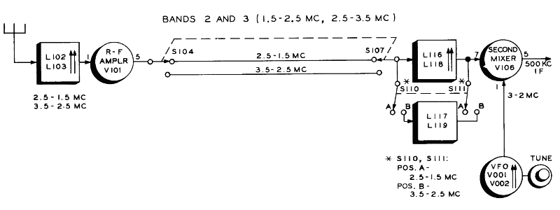
See below the 51J-5 adjusting process for these bands, which is the same for 51J-4 receivers. The alignment procedures below are intended also to be general info to align 51J-4 receivers (omit BFO reversal switch operation, 51J-4 should also have that switch but it doesn't).
Band #2 align procedure: the BFO phase reversal switch is in static position.
- BAND CHANGE switch to band #2 (2.5 to 1.5 Mc).
- Set CW-SSB (BFO ON) and PASSBAND TUNING (BFO) at center (it must generate 500 Kc, see Notes at bottom).
- Set SG to 1.6 Mc and dial to read about 1.6 Mc, check zero beat, set AM (BFO OFF).
- Adjust SG RF out to read on the VTVM about 4 volts.
- Tune cores L102, L116, L118, and then L116, L102, and again
L116, L118 for max indication in the VTVM (if greater than 5 volts decrease SG voltage).
- Set SG to 2.4 Mc and dial to read about 2.4 Mc, CW-SSB, check zero beat, set AM.
- Tune trimmers C104, C174, and C180 for max indication in the VTVM.
Band #3 align procedure: L117 & L119 added in PARalel to L166 and L118, BFO phase reversal switch is in active position.
- BAND CHANGE switch to band #3 (3.5 to 2.5 Mc).
- Set CW-SSB (BFO ON) and PASSBAND TUNING (BFO) at center (it must generate 500 Kc, see Notes at bottom).
- Set SG to 2.6 Mc and dial to read about 2.6 Mc, check zero beat, set AM (BFO OFF).
- Adjust SG RF out to read on the VTVM about 4 volts.
- Tune cores L103, L117, L119, and then L117, L103, and again
L117, L119 for max indication in the VTVM (if greater than 5 volts decrease SG voltage).
- Set SG to 3.4 Mc and dial to read about 3.4 Mc, CW-SSB, check zero beat, set AM.
- Tune trimmers C106, C176, and C182 for max indication in the VTVM.
Error-proof adjustment method to align these two bands.
|
51J-5 (and 4) band 1 conversion table sequence (triple conversion)
INPUT
Band #
[coverage] |
1st mixer XLO (6AK5) |
IF
(var)
Mc |
Band 1 mixer XLO (6AK5) |
IF
(var)
Mc |
2nd mixer LO (6BA7) |
UPPER
IF
LOWER |
Phase inversion, last mixer
BFO RELAY position |
PASSBAND TUNING frequencies
UPPER to LOWER |
Band #1
Odd band
[0.5→1.5 Mc]
Tuning: L101 L110 |
[12 Mc XLO]
High-side mixer
12 Mc XLO
|
11.5
to
10.5
L114 |
[8 Mc XLO]
Low-side mixer
8 Mc XLO |
3.5
to
2.5 |
Adjusted ↑↑↑
(Band #3)
3→2 Mcs LO
Low-side mixer
3.5 in - 3 Mc LO
2.5 in - 2 Mc LO |
499 Kc
500 Kc
501 Kc |
YES, thus:
An Upper sideband signal is now an internal LSB signal
A Lower sideband signal is now an internal USB signal
SIDEBAND INVERSION |
BFO locates freqs at:
Full left UPPER: 503.000
CENTER: 500.000 cs.
Full right LOWER: 498.000
51J-5 BFO relay: Active.
AUTOCORRECTED |
Block diagram of the 51J-5 (and 4), band 1.
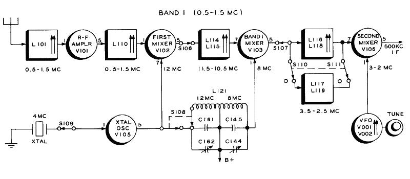
See below the 51J-5 adjusting process for band #1, which is the same for the 51J-4 receiver (omit BFO reversal switch operation, 51J-4 should also have that switch but it doesn't).
Band #1 align procedure: A high-side conversion + a low-side conversion + low-side conversion (Band #3 that is already adjusted). BFO phase reversal switch is in active position.
- BAND CHANGE switch to band #1 (0.5 to 1.5 Mc).
- Set CW-SSB (BFO ON) and PASSBAND TUNING (BFO) at center (it must generate 500 Kc, see Notes at bottom).
- Set SG to 0.6 Mc and dial to read about 0.6 Mc, check zero beat, set AM (BFO OFF).
- Adjust SG RF out to read on the VTVM about 4 volts.
- Adjust core L114 so that it is about in the same position in the inductor as the cores in L116 and L118.
- Tune core L101 and L110 for max indication in the VTVM (if greater than 5 volts decrease SG voltage).
- Tune trimmer C140 for a maximum indication. Two peaks may be found, use peak with higher value of capacitance.
- Set SG to 1.4 Mc and dial to read about 1.4 Mc, CW-SSB, check zero beat, set AM.
- Tune trimmers C102 and C119, for max indication in the VTVM.
- Tune core L115 for max indication in the VTVM.
- Repeat 0.6 and 1.4 Mc tuning procedures until no further increase in output.
Error-proof adjustment method to align this band.
|
51J-5 (and 4) bands 4 thru 30 conversion table sequence (double conversion)
INPUT
Band #number
[signal coverage] |
1st mixer XLO (6AK5) |
IF(var) |
2nd mixer LO (6BA7) |
UPPER
IF
LOWER |
Phase inversion in last mixer
BFO RELAY position |
PASSBAND TUNING frequencies
UPPER (left) to LOWER (right)
Relative to the INPUT signal |
Band #4
Even band
[3.5→4.5 Mc] |
[6 Mc XLO]
High-side mixer
6 Mc XLO |
2.5 Mc
to
1.5 Mc |
Adjusted ↑↑↑
(Band #2)
3→2 Mcs LO
High-side mixer
3 Mc LO - 2.5 in
2 Mc LO - 1.5 in |
501 Kc
500 Kc
499 Kc | NO, input signal unchanged.
An Upper sideband signal is an internal USB signal
A Lower sideband signal is an internal LSB signal
NULL effect (2 inversions) |
BFO locates frequencies at:
Full left UPPER: ±497.000 cs.
CENTER: 500.000 cs.
Full right LOWER: ±503.000 cs.
51J-5 BFO relay: Pasive (static).
AUTOCORRECTED | Band #5
Odd band
[4.5→5.5 Mc]
|
[8 Mc XLO]
High-side mixer
8 Mc XLO |
3.5 Mc
to
2.5 Mc | Adjusted ↑↑↑
(Band #3)
3→2 Mcs LO
Low-side mixer
3.5 in - 3 Mc LO
2.5 in - 2 Mc LO |
499 Kc
500 Kc
501 Kc | YES, thus:
An Upper sideband signal is now an internal LSB signal
A Lower sideband signal is now an internal USB signal
SIDEBAND INVERSION |
BFO locates frequencies at:
Full left UPPER: ±503.000 cs.
CENTER: 500.000 cs.
Full right LOWER: ±497.000 cs.
51J-5 BFO relay: Active (operated).
AUTOCORRECTED |
Bands #6 to #30 the SAME in groups of TWO (6-7 / 8-9 /... .../ 27-28 / 29-30). See the table at bottom.
|
Block diagram of the 51J-5 (and 4), bands 4 thru 30.

See below the 51J-5 adjusting process for these bands, which is the same for 51J-4 receivers. That long group of frequencies is divided into three ranges: Bands #4 → #7, Bands #8 → #15, and Bands #16 → #30. Each range has their specific coils, trimmers, and settings; these aligns are band-pack style, similar to that used on the 75A-4 to adjust the 11 and 10 meter bands.
Band #4 to band #7 range.
- BAND CHANGE switch to band #4.
- Set CW-SSB (BFO ON) and PASSBAND TUNING (BFO) at center (it must generate 500 Kc, see Notes at bottom).
- Set SG to 4 Mc and dial to read about 4 Mc, check zero beat, set AM (BFO OFF).
- Adjust SG RF out to read on the VTVM about 4 volts.
- Tune cores L104, L107, L111, for max indication in the VTVM (if greater than 5 volts decrease SG voltage).
- BAND CHANGE switch to band #7.
- Set SG to 7 Mc and dial to read about 7 Mc, CW-SSB, check zero beat, set AM.
- Tune trimmers C108, C120, C128 for max indication in the VTVM.
- Repeat tuning procedures at 4 Mc and 7 Mc until no further increase in output.
Band #8 to band #15 range.
- BAND CHANGE switch to band #8.
- Set CW-SSB (BFO ON) and PASSBAND TUNING (BFO) at center (it must generate 500 Kc, see Notes at bottom).
- Set SG to 8 Mc and dial to read about 8 Mc, check zero beat, set AM (BFO OFF).
- Adjust SG RF out to read on the VTVM about 4 volts.
- Tune cores L105, L108, L112, for max indication in the VTVM (if greater than 5 volts decrease SG voltage).
- BAND CHANGE switch to band #15.
- Set SG to 15 Mc and dial to read about 15 Mc, CW-SSB, check zero beat, set AM.
- Tune trimmers C110, C122, C130 for max indication in the VTVM.
- Repeat tuning procedures at 8 Mc and 15 Mc until no further increase in output.
Band #16 to band #30 range.
- BAND CHANGE switch to band #16.
- Set CW-SSB (BFO ON) and PASSBAND TUNING (BFO) at center (it must generate 500 Kc, see Notes at bottom).
- Set SG to 16 Mc and dial to read about 16 Mc, check zero beat, set AM (BFO OFF).
- Adjust SG RF out to read on the VTVM about 4 volts.
- Tune cores L106, L109, L113, for max indication in the VTVM (if greater than 5 volts decrease SG voltage).
- BAND CHANGE switch to band #30.
- Set SG to 30 Mc and dial to read about 30 Mc, CW-SSB, check zero beat, set AM.
- Tune trimmers C124, C132, and ANT TRIM for max indication in the VTVM.
- Repeat tuning procedures at 16 Mc and 30 Mc until no further increase in output.
Error-proof adjustment method to align these three groups of bands.
|
→ References and adjustment locations on the 51J-4 chassis for performing alignments (same as on the 51J-5) ←
51J-5 (and 4): Range-based IF signal phase operation.
| 51J-4 and 51J-5 |
51J-5 BFO (PT) → IF Passband |
Band
# (type) |
Range (Mcs) |
Eff XLO Injection (Mcs)
[Conversion positioning] |
Xtal
(Mcs) |
PTO
(Mcs) |
Eff phase inversion |
Upper/Lower
(midpoint, Cicles) |
Upper/Lower
shift* (Feat) |
| 01 (Odd) |
0.5 → 1.5 |
12 and 8 [↑ + ↓ + ↓] |
4 |
2
to
3
The
Real
M
I
X
E
R |
YES |
501.500 / 498.500 |
YES (OK)
|
| 02 (Even) |
1.5 → 2.5 |
none-single conversion [↑] |
no |
YES |
498.500 / 501.500 |
NO (No OK**) |
| 03 (Odd) |
2.5 → 3.5 |
none-single conversion [↓] |
no |
NO |
501.500 / 498.500 |
YES (No OK**) |
| 04 (Even) |
3.5 → 4.5 |
6 [↑ + ↑] {2.5 to 1.5 out}
|
6 |
NO |
498.500 / 501.500 |
NO (OK) |
| 05 (Odd) |
4.5 → 5.5 |
8 [↑ + ↓] {3.5 to 2.5 out} |
8 |
YES |
501.500 / 498.500 |
YES (OK) |
| 06 (Even) |
5.5 → 6.5 |
8 [↑ + ↑] {2.5 to 1.5 out} |
8 |
NO |
498.500 / 501.500 |
NO (OK) |
| 07 (Odd) |
6.5 → 7.5 |
10 [↑ + ↓] {3.5 to 2.5 out} |
10 |
YES |
501.500 / 498.500 |
YES (OK) |
| 08 (Even) |
7.5 → 8.5 |
10 [↑ + ↑] {2.5 to 1.5 out} |
10 |
NO |
498.500 / 501.500 |
NO (OK) |
| 09 (Odd) |
8.5 → 9.5 |
12 [↑ + ↓] {3.5 to 2.5 out} |
12 |
YES |
501.500 / 498.500 |
YES (OK) |
| 10 (Even) |
9.5 → 10.5 |
12 [↑ + ↑] {2.5 to 1.5 out} |
12 |
NO |
498.500 / 501.500 |
NO (OK) |
| 11 (Odd) |
10.5 → 11.5 |
14 [↑ + ↓] {3.5 to 2.5 out} |
14 |
YES |
501.500 / 498.500 |
YES (OK) |
| 12 (Even) |
11.5 → 12.5 |
14 [↑ + ↑] {2.5 to 1.5 out} |
14 |
NO |
498.500 / 501.500 |
NO (OK) |
| 13 (Odd) |
12.5 → 13.5 |
16 [↑ + ↓] {3.5 to 2.5 out} |
8 |
YES |
501.500 / 498.500 |
YES (OK) |
| 14 (Even) |
13.5 → 14.5 |
16 [↑ + ↑] {2.5 to 1.5 out} |
8 |
NO |
498.500 / 501.500 |
NO (OK) |
| 15 (Odd) |
14.5 → 15.5 |
18 [↑ + ↓] {3.5 to 2.5 out} |
9 |
YES |
501.500 / 498.500 |
YES (OK) |
| 16 (Even) |
15.5 → 16.5 |
18 [↑ + ↑] {2.5 to 1.5 out} |
9 |
NO |
498.500 / 501.500 |
NO (OK) |
| 17 (Odd) |
16.5 → 17.5 |
20 [↑ + ↓] {3.5 to 2.5 out} |
10 |
YES |
501.500 / 498.500 |
YES (OK) |
| 18 (Even) |
17.5 → 18.5 |
20 [↑ + ↑] {2.5 to 1.5 out} |
10 |
NO |
498.500 / 501.500 |
NO (OK) |
| 19 (Odd) |
18.5 → 19.5 |
22 [↑ + ↓] {3.5 to 2.5 out} |
11 |
YES |
501.500 / 498.500 |
YES (OK) |
| 20 (Even) |
19.5 → 20.5 |
22 [↑ + ↑] {2.5 to 1.5 out} |
11 |
NO |
498.500 / 501.500 |
NO (OK) |
| 21 (Odd) |
20.5 → 21.5 |
24 [↑ + ↓] {3.5 to 2.5 out} |
12 |
YES |
501.500 / 498.500 |
YES (OK) |
| 22 (Even) |
21.5 → 22.5 |
24 [↑ + ↑] {2.5 to 1.5 out} |
12 |
NO |
498.500 / 501.500 |
NO (OK) |
| 23 (Odd) |
22.5 → 23.5 |
26 [↑ + ↓] {3.5 to 2.5 out} |
13 |
YES |
501.500 / 498.500 |
YES (OK) |
| 24 (Even) |
23.5 → 24.5 |
26 [↑ + ↑] {2.5 to 1.5 out} |
13 |
NO |
498.500 / 501.500 |
NO (OK) |
| 25 (Odd) |
24.5 → 25.5 |
28 [↑ + ↓] {3.5 to 2.5 out} |
14 |
YES |
501.500 / 498.500 |
YES (OK) |
| 26 (Even) |
25.5 → 26.5 |
28 [↑ + ↑] {2.5 to 1.5 out} |
14 |
NO |
498.500 / 501.500 |
NO (OK) |
| 27 (Odd) |
26.5 → 27.5 |
30 [↑ + ↓] {3.5 to 2.5 out} |
10 |
YES |
501.500 / 498.500 |
YES (OK) |
| 28 (Even) |
27.5 → 28.5 |
30 [↑ + ↑] {2.5 to 1.5 out} |
10 |
NO |
498.500 / 501.500 |
NO (OK) |
| 29 (Odd) |
28.5 → 29.5 |
32 [↑ + ↓] {3.5 to 2.5 out} |
10.67 |
YES |
501.500 / 498.500 |
YES (OK) |
| 30 (Even) |
29.5 → 30.5 |
32 [↑ + ↑] {2.5 to 1.5 out} |
10.67 |
NO |
498.500 / 501.500 |
NO (OK) |
51J-5 tuning knob (PTO): 4 turns→100 Kc, 40 turns→1 Mc.
[↑] High-Side mixing. [↓] Low-Side mixing. |
∑ crystals: 10. |
* Internal BFO Passband Tuning inversion.
** It needs to be corrected by manual shift. |
Notes:
- "51J-4 and 51J-5" = All that info is useful for 51J-4.
- Using 51J-4, SSB reception depending band type must be corrected by trial and error by
rotating the BFO from side to side, which is not very technical precisely. Collins conceals this "feature" in a "technical" way in section 3 page 4 of the 51J-4 manual. This is corrected in 51J-5 through a relay that selects the appropriate side range of the BFO based on the band type. The exception to this operation are bands #2 and #3, where adjustment is made by manual reversal of the Upper/Lower PASSBAND TUNING knob (same as with the 75A-4 when the 160 meter band is selected for SSB reception).
- BFO operation (CW-SSB) is included in the PT feature but without changing the receiving frequency (introduced in 75A-4).
- Accurate checking of the BFO center frequency should be done by double reading on an even and an odd band. 51J-5 only, see (*) above.
- It is important to take into account that the PT operation changes both the BFO and PTO frequencies, but maintains synchronization between those two settings. Therefore, an SSB or CW signal should have the same tone throughout the offset, just as on 75A-4.
- The effective PT area is limited by the bandwidth of the mechanical filter in use, so a 3.1 Kc MF has approximately 3 Kc of scanning area. The effective area is always slightly smaller than the nominal bandwidth of the MF in use.
- The signal must be received correctly first, and then PASSBAND TUNING may be used. SSB signals should be tuned using the classic configuration of signal in the center and BFO at a side, thus the PT knob should be located on the correct side: UPPER for LSB signals and LOWER for USB signals, except in bands #2 and #3 where the PT U/L positioning must be reversed (as with 75A-4 on the 160 meter band).
- Best reception occurs when PASSBAND TUNING selects the correct BFO side frequency taking into account the MF bandwidth. Usually for 6.0 and 3.1 MFs the best U/L settings are the midpoints specified in the table above. An example of using PASSBAND TUNING, and what it is used for, could be: Listening at 14,210 Kc with the 6.0 mechanical filter and having interference from a signal at 14,214 Kc. PASSBAND TUNING will be at UPPER in its mid-range (BFO at 498,500 Cs). By simply moving the PT knob from 498,500 to 499,500 Cs the interference will "fall off" by the side of the mechanical filter and disappear. PASSBAND TUNING works as it should, both in even and odd bands, with no "prototype problems" like those reported for the model X2 (Fred Hammond Museum - CCA Signal issue #71, I think these are erroneous reports or perhaps the X2 unit needs repair).
- Some mods applied to the 75A-4 are also effective in the 51J-5. In the 51J-5 R46 (75A-4 schematic) has a "Q-killing value" increased than in the 75A-4 (15 Kohm vs 22 Kohm). The dynamics of the IF has been increased by replacing the 15 Kohm value with the value successfully tested in the 75A-4: 68 Kohm (75A-4 and 51J-5 IF input amplifier circuits are the same). These low shunt resistor values are applied when a flat response and adequate bandwidth for a short, flat AVC line design are desired, but this results in the receiver having very little dynamics, making it compact as a brick; 68 Kohms make the circuit more dynamic.
- Like 75A-4, the 51J-5 screen resistor of the first 6BA7 mixing tube (R15) follows the rule of putting low resistance values to give a low Q. The low value chosen here (4K7 ohms) causes even the maximum standard screen voltage for this tube (100 volts) to be exceeded. One difference between 75A-4 and 51J-5 is that the B+ line to the RF amplifier screen grids and mixer tubes has reduced voltage (170 VDC vs 210 VDC), so here the value of R15 can be lower than in the 75A-4; a value of 8K2 ohm is given to R15 which is equivalent to the 15 Kohm given in the 75A-4.
- The "two-handed operation" to minimize the lack of signal-to-noise ratio and the "short" AVC characteristic recommended for the 75A-4 is also recommended for the 51J-5, since the two receivers share the same base design.

|
|
|