| 75A-4 is the sum of a single-band medium wave receiver + a multiband short wave converter.
The mixer system: A coil is tuned by a capacitor to a frequency X, and there is a Variable Local Oscillator with another coil tuned to a frequency Y above or below the frequency of the first coil, both coils have ganged (tandem) tuning. Result: At a given moment the output frequency will be a SINGLE frequency that ALWAYS has the SAME difference input frequency/oscillator frequency. This system offers an output frequency with the advantage of to have Q characteristic. Example: We have an input range of 3.2 to 4.2 Mc and we want an IF of 2 Mc. The VLO must tune from 5.2 to 6.2, the output will be fixed and always 2 Mc.
We can find a mixer system in the 75A-4 starting from the PASSBAND TUNING circuits, but Collins "kills" a good deal of IF Q by means of the R46 resistor in order to have a flat, low impedance, AVC characteristic. This resistor is very important as far as the signal to noise ratio is concerned.
This design is defended in 'Souping Up The 75A-4' that claims that a low AVC characteristic improves the noise figure. In fact, what this
design does is disguise the poor dynamic range of the receiver by the method of keeping the noise in the elbow of the characteristic curve of the tube, and what emerges from the noise (the signal is assumed) is placed on the rising line. The idea is not bad, but it can happen that due to the poor dynamic range, both noise and signal remain in the elbow. As the dynamic range increases by increasing the Q of the IF, the AVC may fall short, and therefore the stronger signals will have "pumping".
The converter system: A coil is tuned by a capacitor to a frequency X, there is a crystal oscillator tuned to a frequency Y above or below the frequency of the first coil; therefore, the LO operates at a fixed frequency. Result: The output frequency will be the difference between the oscillator frequency and the tuned frequency at the input, but since the oscillator is fixed, the output will always be a different frequency with different spacing with the input frequency. The input area will be reproduced at the output in a BLOCK that is an image of the input range, no Q characteristic. Any frequency of this block must be selected by another circuit which will give Q to that frequency. Example: We have an input range of 3.2 to 4.2 Mc and an XLO of 5.7 Mc (current case). The output will be variable and will go from 2.5 Mc (5.7 - 3.2) to 1.5 Mc (5.7 - 4.2).
Basic 75A-4 single conversion MW monoband receiver. Mouseover: 75A-4 double conversion SW multiband.
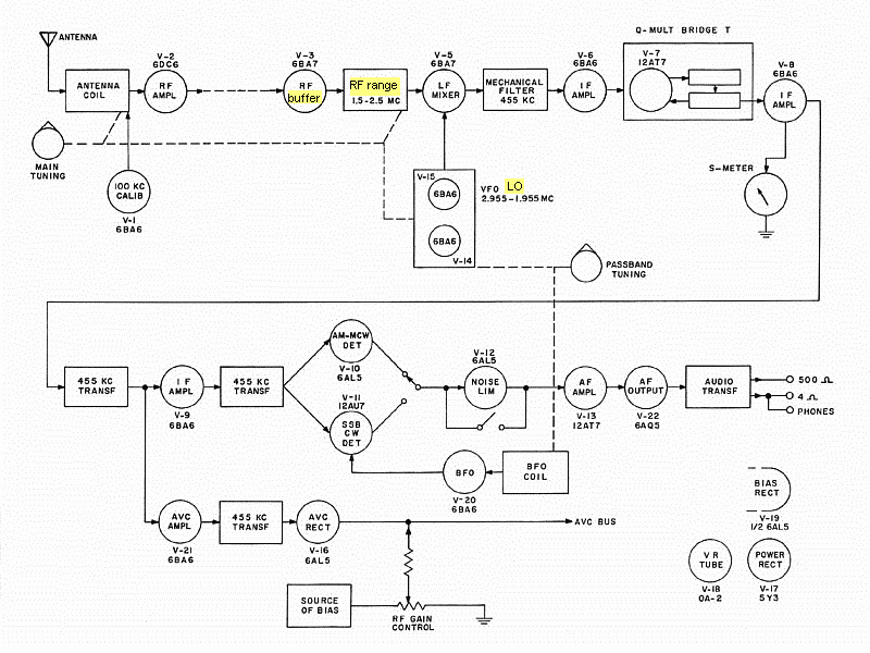
— 75A-4 block diagrams, hover over image to compare single coversion with double conversion.
The PASSBAND TUNING system, a PTO + BFO combo.
The Passband Tuning combo is a 'trick' (or another 'hack') of the 75A-4. Making passband tuning is not complicated (see the so-called VERNIER TUNING on the Hammarlunds HQ-170/180), but making true SSB passband tuning is. Collins did so with results ranging from very good (tuning the passband without changing SSB pitch in order to drop interfering signals beyond the edge of the passband) to questionable (mechanical filter bandwidth dependence). True SSB passband tuning involves coordinated use of the BFO with the LO (VLO, PTO) to maintain correct SSB audio decoding within an exploration area 3 Kcs up and down off center, this feature is highly associated with the response and bandwidth of the mechanical filter in use, which should be flat. Passband Tuning consists of placing the frequencies that are of interest in that response, adding below and removing above and adding above and removing below, that is, performing a certain IF center offset. SSB decoding refers to the distance relationship between the BFO frequency with the tuning operator; if this changes, the BFO must follow the change to maintain intelligibility.
75A-4 processes signals in the center of the RF or IF channel, whether AM, CW, or SSB. 75A-4's BFO works in the same way as in most SSB receivers, it gives a beat note when tuned to one side of the IF channel, but the difference here is the BFO control simultaneously drags the mixer's VLO (local oscillator). The 75A-4's BFO has a peculiar feature, it is a "frozen BFO", an ECO type with a screen grid voltage of only 42 VDC (the 'plate' of the oscillator), and the plate of the BFO tube (V20) works at 14 VDC only! This BFO is another 75A4's low impedance, flat feature design; therefore it is possible that as the tube ages, a lack of BFO energy might be noticeable when receiving strong SSB signals. This BFO can work on SSB in that 'cold way' because it is associated with a product detector, otherwise it could not.
The passband tuning feature can be easily tested by setting SSB, PASSBAND zero, CAL ON, and then tuning zero beat. When PASSBAND TUNING is operated in its 6 Kcs (upper 3 + lower 3), zero beat is maintained because the difference between the tuning point setting and the BFO setting is also maintained. Signal strength and quality may vary depending on the resonance characteristic of the mechanical filter and the circuits that follow it. The optimum tuning area directly depends on the bandwidth of the mechanical filter in use, so the practical effectiveness of the passband tuning operation is somewhat limited (the fine print that is not included in manuals or avertising).
To achieve this feature, Collins did this:
- The tuning operator (LO, VLO, VFO, PTO) has two access modes: PTO shaft and PTO body.
- The PTO shaft has a dial that indicates tuned frequency, and is operated by the 4:1 tuning reducer inside the tuning knob.
- If the PTO shaft rotates and the body remains static, the tuned frequency on the dial changes.
- If the PTO shaft is static but the body changes, the tuned frequency changes, but not on the dial (*).
- A movement of the shaft to the right is equal to a movement of the body to the left.
- A movement of the shaft to the left is equal to a movement of the body to the right.
- To maintain intelligibility, the BFO (which is adjusted in a certain way) follows the movement of the tuning operator.
- Therefore, a mechanical system is required to carry out all this work, see pic below.
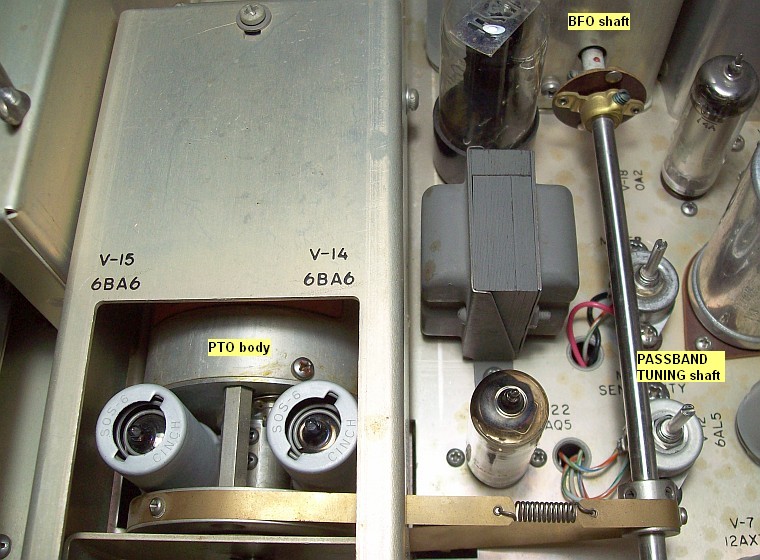
— Passband Tuning assembly, hover over image to see Passband Tuning operation (QST, April 1955).
Actual setting status of the PTO + BFO combo is easily verifiable as described above. On doubts, it is best to read the manual since it is rare for this assembly to come out of adjustment on its own except in cases of intensive use. If you need to adjust this tuning combo, before acting you must be very clear about how the PTO is adjusted, its synchronization with the BFO, and how the set operates in the 75A-4 circuit.
(*) A DIAL DRAG mechanism on the lower front panel was initially designed with the intention of preventing the PTO shaft (and dial) from moving due to internal body/shaft friction when operating PASSBAND TUNING. The dial drag effect was nullified with the incorporation of the special 4:1 gear reduction knob that incorporates resistance to movement due to its reduction effect; then the panel label changed to DIAL LOCK.
75A-4 Alignment process. Setup:
- → VTVM or DVM with fast gate... or the simplest: S-Meter. As an example, if the S-Meter is used, the signal generator should be
set to give an indication between S-9 and +20, this ensures correct sensitivity when adjusting coils and trimmers.
- → Signal Generator with dummy-antenna coupler and test-lead coupler (or use capacity coupling to a wire connected as an "antenna"). Use a stable signal generator, if the SG is not stable the adjustments should be made with the widest possible mechanical filter, since the generated signal can suddenly go from S9 to S0 when the drift "drops" on the edge of the filter. Due this, when adjusted through the 3.1 Kc filter, the maximum allowable drift of the SG is about 2.6 Kc.
- → Set receiver for AM reception (passband at center), AVC FAST, RF gain max, NL and REJECTION TUNING OFF.
- → Set ANT TRIM one mark off center at left (after adjustment, this will allow to tune the max signal level in the center on the 20 meter band and above).
Alignment of the 'basic 75A-4 receiver' (160-meter 1 Mc range → single conversion 75A-4)
What should happen, but it rarely happens:
- When the Megacycle dial reads 2.5 Mc and the Kilocycle dial reads zero, the PTO (VLO) should oscillate at 2.955 Mc.
- When the Megacycle dial reads 2.4 Mc and the Kilocycle dial reads zero, the PTO (VLO) should oscillate at 2.855 Mc.
- And so on, until...
- When the megacycle dial reads 1.5 Mc and the Kilocycle dial reads zero, the PTO (VLO) should oscillate at 1.955 Mc.
- PTO frequency can be accurately checked with a frequency counter on the control grid of the 2nd mixer, V5 pin 2.
- When the passband tuning is in the center, the BFO frequency should be 455,000 cs.
- And when setting CAL you should hear zero beat.
- BFO frequency can be accurately checked with a frequency counter on the control grid of section 2 of V11, pin 7.
Dial Tracking Test performed on the 1-Mc area of the 160 meter range (where all the frequencies land)
| Mc DIAL |
PTO fr at zero beat (±) |
Shift from zero beat to 0 mark (Kc dial) |
|
Mc DIAL |
PTO fr at zero beat (±) |
Shift from zero beat to 0 mark (Kc dial) |
| 1.5 |
1,955,040 |
0 (hairline on 0) |
|
2.1 |
2,555,060 |
-1520 |
| 1.6 |
2,055,020 |
0 |
|
2.2 |
2,655,060 |
-1720 |
| 1.7 |
2,155,060 |
0 |
|
2.3 |
2,755,080 |
-2080 |
| 1.8 |
2,255,060 |
0 |
|
2.4 |
2,855,080 |
-1830 |
| 1.9 |
2,355,040 |
-450 (scroll to 0) |
|
2.5 |
2,955,070 |
-1480 |
| 2.0 |
2,455,080 |
-800 |
|
BFO at center '0' is 455,040 cs. |
Procedure:
- PASSBAND TUNING at 0 (BFO at center), CW-SSB, AVC FAST, CALibrator ON.
- Frequency Counter on V5, pin 2.
- Dial at 1.5 Mc and set zero beat.
- Match zero beat with '0' mark and set it with the hairline (ZERO ADJ).
- Take FC readings on all subsequent 100 Kc.
- - Sign values mean that the zero beat on each 100 Kc does not reach (-) or exceed (+) the 0 Kc mark on the dial for the indicated number of cycles (FC in REL).
- - There is a linearity fault in the synchronization of the PTO frequencies with Kc dial marks. PTO frequency offset needs to be tweaked, but Collins designed the adjustment of these PTOs with little practicality.
- - Nonlinearity occurs when the total length of the PTO frequency range does not match the total length and frequency range of the Kc dial. The movement of the PTO from the start frequency to the end frequency is "longer" or "shorter" than the Kc dial marking. Thus, the PTO frequency area must be "narrowed" or "stretched" to match the Kc dial markings.
|
PTO test: Theory and reality don't match, but it is clear that 75A-4 would allow total frequency precision without the use of a calibrator when it was mfg adjusted, and this only can be said of FEW receivers of the time. On vintage equipment if the current performance is within reasonable margins it is better not to be a perfectionist. This is what happened on this unit (max tracking error is 2 Kc, it can be corrected with ZERO SET and CAL) so no action has been taken on the VLO or the BFO (the passband tuning combo).
Alignment process. The following relies on the passband tuning combo LO (V-14+V-15) & BFO (V-20) being correctly adjusted.
→ 455 Kc fixed IF setting: Set AVC FAST.
- AVC amp setting: Signal Generator to 455 Kc with test-lead coupler, active lead to pin 5 of V-8 (B+ here!), the other to ground.
- Connect VTVM to the AVC test point and increase SG output until the VTVM reads midscale in the 0 to 15 -VDC range.
- Adjust cores of T-4 (AVC amp) for maximum indication.
- IF amp, in and out setting: Signal Generator to 455 Kc with test-lead coupler, active lead to pin 1 of V-8, the other to ground.
- Connect VTVM to the Diode-Load test point and increase SG output until the VTVM reads midscale (-15 VDC range).
- Adjust cores of T-3 (IF to detectors) for maximum indication.
- Adjust L-27 (IF in amp) for maximum indication.
- Recheck T-3 and L-27 for maximum indication.
- The first IF amplifier (V6 tube) does not need any adjustment because its plate loading is aperiodic (a 2 mH choke and a Q-killing shunt resistor, hence wideband response).
This 455 Kc IF setting is required to be exact because the 75A-4 has 455 Kc mechanical filters.
→ 1.5 to 2.5 Mcs RF setting: SG terminated by a dummy antenna connected to the antenna plug (or capacitive coupling).
- Limit the output level of the signal generator to the half scale on the receiver indicator, e.g. S9+ using S-meter.
- Lo-Fr adjust: Signal generator and receiver to 1.6 Mc, PASSBAND center, AVC FAST, SSB, tune zero beat, select AM.
- Adjust slugs T-1, L-18, L-22, in that order, for max output indication on the S-meter or voltage in Diode-load.
- Hi-Fr adjust: Signal generator and receiver to 2.5 Mc(1), PASSBAND center, AVC FAST, SSB, tune zero beat, select AM.
- Adjust trimmers C-7, C-53, C-56, in that order, for max output on the S-meter or voltage in Diode-load.
- The dial may not read exactly 1.6 and 2.4; don't worry, forget it, ZERO SET correct this.
- Repeat/retouch Lo-Hi adjusts until no further increase is noted in output.
- Error-proof adjustment method.
- The correct adjustment is noted when the response throughout the 1 Mc range is about the same. That is, the S-Meter (or VTVM) should read similar at any point in the tuning range, although the low range (center to 1.5) will give a little more gain. This is the area needed to receive signals from the converter. If there are then inequalities in the rest of the bands, the fault lies with the converter, not the receiver.
This adjusts the backbone of the 75A-4 (the 'basic 75A-4 receiver'). A defect in these settings will be reflected in all bands.
(1) Choosing 2.4 according to the manual, the response drops a bit when tuning towards the 2.5 end (but YMMV). I recommend to choose 2.5 (end of the band) because we are building the area in which all the frequencies have to be displayed, and this depends on how flat the response is in this band. This assures a PERFECT result.
Note that this procedure is very similar to the procedure applied to 5-tube receivers. The adjustment protocol is to go from the low frequencies to the high frequencies. First the IF, and inside the IF first the detector transformer and the AGC transformer, going backwards next is the IF amplifier. Second is the RF section, first is the low frequency that is adjusted by inductance, and second the high frequency that is adjusted by capacitance; the same applies for the RF converter.
Alignment of the 80 to 10 meter RF stage converter (double conversion 75A-4)
What should happen, but it rarely happens:
- Setting 80, when the Megacycle dial reads 3.2 Mc and Kilocycle dial zero, a 2,500,000 cs output signal should be generated.
- Setting 80, when the Megacycle dial reads 4.2 Mc and Kilocycle dial zero, a 1,500,000 cs output signal should be generated.
- Setting 80, when the Megacycle dial and kilocycle dial read any frequency between the above two, a frequency between 2,500,000 cs and
1,500,000 cs should be generated.
- Setting 40, same with dial readings of 6.8 and 7.8 Mc. Setting 20 same with 14 and 15 Mc. And so on...
- With passband tuning in the center, setting CAL and CW-SSB you should hear a zero beat at any multiple of 100 kcs.
- The XLO frequency can be checked (not accurately) with a digital frequency counter on pin 3 of V4, cathode, or accurately using this procedure (it avoids any loading effect).
1) XLO adjustment. Which consists of V-4 (12AT7) + (L-11 to L-17 coils).
- Prepare VTVM with the DC tip (which has a 1 Mohm resistor inside it) and select the -DC 15 volt scale.
- Connect the DC tip to pin 2 of V-3 (XLO output to the 1st mixer control grid). This measures the rectified voltage (DC) present due the effect of the control-grid/ground "diode". Voltage varies from 2 to 10 volts depending on the converter band selected.
- Set max output reading on the VTVM by setting...
- Band switch to 80 and adjust L-12.
- Band switch to 40 and adjust L-13.
- Band switch to 20 and adjust L-14.
- Band switch to 15 and adjust L-15.
- Band switch to 11 and adjust L-16.
- Band switch to 10 and adjust L-17.
- Band switch to 10 and adjust L-11.
- These coils have influence on the frequency of the crystal, so there is a certain level of xtal-fr adjustment (about 2 Kc max, but depending on band and Xtal activity). This permits to reduce calibration errors within bands, and also the adjust of the XLO to the exact nominal frequency of the crystal, if it is needed.
- More voltage injected to the mixer: More noise due (but) conversion gain increases.
- Less voltage injected to the mixer: Less noise due (but) conversion gain decreases.
- The noise of a tube is very low compared to the noise coming through the antenna. The practical noise figure is HOW a tube or a circuit processes
noise, not specifically the one it has (lots of confusion on this). High transconductance tubes process noise better due to the effect of highlighting the signal over it. This need was given by the design of TV video IF channels, and front-end high frequency circuits.
- When adjusting clockwise, the XLO frequency decreases, counterclockwise increases; but it only works within a limited frequency range, leaving this range the XLO stops oscillating.
- Check the calibrator to make sure the frequency is 100 Kc exact on a frequency counter, see pic.
- Zero beat matching on the dial can be adjusted CAL ON/CW SSB and by tweaking the XLO coils... until a certain point.
- Turn the BAND switch successively to each band, adjust each coil, but there is a limit... when the XLO stops oscillating.
- Confirm XLO oscillating frequency for each band on a frequency counter, see pic.
This circuit ensures the correct level of local frequency injection to the second mixer to perform heterodyne work to the converter tube, it does not do much else. If checking the frequencies it works OK (to find out how click on the link above), it is most likely not necessary to do anything. My POV is not to adjust things that do not need to be adjusted, but it needs to be checked first.
2) RF amp - Mixer adjustment. Which consists of V-2 (6DC6) RF amp with its input and output coils.
The following procedure relies on the XLO (V-4) being correctly adjusted for each band (above). Proceed as explained below using the band alignment sequence chart.
- This adjusts the input coils to the RF amp (V-2, 6DC6) and the inter-stage coils to the 1st mixer (in fact the converter).
- Same receiver configuration as for the 160 meter band.
- The following steps must be carried out with the data specified in the table below and for each band.
- Lo-Fr adjust: Signal generator and receiver tuned to the LOW-END frequency depending on BAND (table below).
- SG level to half scale on the meter used; e.g. S9+ with S-meter. PASSBAND center, AVC FAST, SSB, tune zero beat, select AM.
- Adjust L coils for max output on the S-meter or voltage in Diode-load. Adjustment sequence (first/later) is indicated below.
- Hi-Fr adjust: Signal generator and receiver tuned to the HIGH-END frequency depending on BAND (table below).
- SG level to half scale on the meter used; e.g. S9+ with S-meter. PASSBAND center, AVC FAST, SSB, tune zero beat, select AM.
- Adjust C trimmers for max output of the S-meter or voltage in Diode-load. Adjustment sequence (first/later) is indicated below.
- Repeat/retouch Lo-Hi adjusts until no further increase is noted in output.
- The 10 and 11 meter bands have a special procedure, see (b).
75A-4 RF converter band alignment sequence chart and simplified heterodyne operation
| BAND |
LOW END
(set Mcs) |
RF L
(first) |
ANT L
(later) |
HIGH END
(set Mcs) |
RF C
(first) |
ANT C
(later) |
Dial Range
Mcs |
XLO
Mcs |
IF OUT
Mcs |
| 80 |
3.3 |
L-6 |
T-2 |
4.1 |
C-23 |
C-8 |
3.2 to 4.2 |
5.7 |
2.5
to
1.5 |
| 40 |
6.9 |
L-7 |
L-1 |
7.7 |
C-26 |
C-11 |
6.8 to 7.8 |
9.3 |
| 20 |
14.0 (a) |
L-8 |
L-2 |
14.9 |
C-28 |
C-13 |
14 to 15 |
16.5 |
| 15 (>6-1957) |
20.9 |
L-9 |
L-3 |
21.7 |
C-30 |
C-15 |
20.8 to 21.8 |
23.3 |
| 15 (6-1957+) |
20.6 |
L-9 |
L-3 |
21.4 |
C-30 |
C-15 | 20.5 to 21.5 |
23 |
| 10 Lo (b) |
28.1 |
L-10 |
T-7 |
28.9 |
C-32 |
C-16 |
28 to 29 |
30.5 |
| 10 Hi (b) |
29.5 |
Ant-Tr |
- |
- |
C-17 |
- |
29 to 30 |
31.5 |
| 11 (b) |
27.1 |
Ant-Tr |
- |
- |
C-31 |
- |
26.5 to 27.5 |
29 |
→ Location and reference of components on the chassis to make adjustments ←
(a) Manual says 14.1 but it is better to choose 14.0 because this band starts at 14 Mc on the dial. Choosing 14.0 avoids the dropping slope of the lower end of the band that occurs when choosing 14.1.
(b) This is a part of the 27.1 to 30 Mc range that is divided into three bands, 26.5 to 27.5, 28 to 29 and 29 to 30 Mc. This range is in fact a "27.1 to 30 Mc band" containing sections, an economical design, and must be aligned FM style. First the band centered in the range (28 to 29), second the last one (29 to 30), and third the first one (26.5 to 27.5). Ant-Tr = ANT TRIM on the panel (C-18).
If an adjustment progresses very slowly (or does not show any sign of progress) and with a very gentle peak, it can be surely assumed that the associated tuning capacitor is defective.
75A-4 front-end and Converter tuning system data
A common characteristic of the Collins gear is the use of inductance tuning, but it is not because inductance tuning is better than capacitance tuning, Collins is forced to use it because his interest was focused on achieving maximum dial accuracy combined with minimal frequency drift. Due this, Collins' designs were based in the converter heterodyne system (LO in low frequency, Xtal in high frequency), and not in the mixer heterodyne system (LO in high frequency, Xtal in low frequency; e.g. Hammalunds). The great advantage of the converter heterodyne system is that it operates by tuning on low frequencies, hence stability (frequency drift) is much better than in the mixer system. The big disadvantage is that it is more complicated to make, and that is why the Collins have all that “elevators” paraphernalia using oval cams. Needless to say, it is also more expensive for that reason; achieving "modern" stability took a lot of money in the 50s.
See below for the economical front-end tuning system applied to the 75A-4. This parallel coil design causes the Q to be low; and therefore low Q circuit = wide band = noisy circuit. Parallel coils cause, in addition to reducing inductance, a Q-reducing effect. A visual definition of the Q-factor for amateurs is the resonant frequency divided by its bandwidth, although the official definition of a coil's Q-factor is its inductive reactance divided by its series resistance. 75A-3, 2 and 1 have a very similar front design, but the main difference of version 4 with the rest is that 75A-4 also has a low Q IF design to perfectly adapt to the flat top of the mechanical filters and the PASSBAND TUNING feature. 75A-4 is a low Q radio, but don't confuse it with low gain! Precisely... if we remove gain we will have the feeling that we are removing noise (that's why I don't trust the comments of some modifications). The Q factor in a 75A-4 is provided solely by the Q of the mechanical filter!!! The inductance tuning in one band is also used in the others by placing fixed inductances in parallel (the 'par' definition below, the inductance of two coils connected in parallel is less than the inductance of either coil). This design is to blame for version 4 being noisy, not the internal noise of the tubes (version 3 uses also 6BA7 mixer tubes).
75A-4 RF active tuning components per band
75A-4 Front-End
|
80 to 10 meter converter (see text) |
| Bands |
ANT T/L |
ANT Cp |
ANT TRIM (C-18) |
RF L |
RF Cp |
RF Ct |
XLO-L |
XLO-C |
| 160 |
sec T-1 Per-Tun,
plus L-18, L-22. |
C-6 390pF |
C-7 8-50pF + C-18
plus C-53, C-56. |
- | - |
- | - | - |
| 80 |
sec T-2 Per-Tun |
C-9 650pF |
C-8 8-80pF + C-18 |
L-6 Per-Tun |
C-24 650pF |
C-23 8-50pF |
L-12 |
C-40 220pF
|
| 40 |
L-1 par sec-T2 |
C-10 300pF |
C-11 8-50pF + C-18 |
L-7 par L-6 |
C-25 300pF |
C-26 8-50pF |
L-13 |
C-41 130pF |
| 20 |
L-2 par sec-T2 |
C-12 120pF |
C-13 8-50pF + C-18 |
L-8 par L-6 |
C-27 120pF |
C-28 8-50pF |
L-14 |
C-42 120pF |
| 15 |
L-3 par sec-T2 |
C-14 68pF |
C-15 8-50pF + C-18 |
L-9 par L-6 |
C-29 68pF |
C-30 8-50pF |
L-15 |
C-43 110pF |
| 11 |
L-4 par sec-T2 |
C-22 24pF |
C-16 5-25pF + C-18 |
L-10 par L-6 |
C-50 39pF |
C-31 5-25pF |
L-16 |
C-44 56pF |
| 10 Lo |
L-5 par sec-T2 |
C-22 24pF |
C-16 5-25pF + C-18 |
L-10 par L-6 |
C-50 39pF |
C-32 5-25pF |
L-17 |
C-45 47pF |
| 10 Hi |
L-6 par sec-T2 |
C-22 24pF |
C-16 5-25pF + C-18 |
L-10 par L-6 |
C-50 39pF |
C-17 5-25pF |
L-11 |
C-51 47pF |
color = RF section of the "75A-4 160 meter band receiver" (front-end of the basic 75A-4 receiver).
C-18 = ANT TRIM control on panel, variable, 2-20 pF, initially adjusted at half capacity.
Per-Tun = permeability tuning, RF tuning + LO tuning (tandem-equivalent) = [T-1, T-2, L-6 {converter}, L-18, L-22] (RF), [L-200+L-201] (LO).
par = connected parallel to | sec = secondary of | Lo = low frequency section | Hi = high frequency section
Cp = main tuning capacity | Ct = trimmer adjust | T = transformer | L = inductance | C= capacitance
Chassis coil cores on which the tuning knob acts, 5: sec of T1, sec of T2, L-6, L-18, and L22 (note error in the schematic for L-6). |
That's why the 75A-4's low signal-to-noise ratio is impossible to fix because it's a design feature, it can only minimize the effect to a certain extent. The 75A-4 is a good receiver for only medium to strong signals, the weak ones will always be below the noise. The only way to minimize this problem is to use the mechanical filter closest to the signal amplitude and increase the dynamic range of the signal as much as possible; this is discussed on the modifications page.
 |