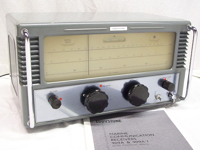
The Eddystone 909A is a 7 tube AC/DC single conversion
communications superhet receiver having a single stage of RF amplification and two IF stages designed
specifically for marine use in the band 1.6 to 4.7 Mcs. This coverage is
split into two switched ranges and rapid selection of the HF Distress and
Calling Channel (2182 Kcs) that may be relayed via a low impedance output
to a monitor speaker located on the ship's bridge.
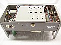
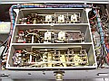
The RF section, embedded into a cast alloy chassis (see the 4th photo above), employs a 12BA6 vari-mu RF pentode from the aerial via a bandpass coupled tuning circuit which is composed by two ferrite inductors.
The primary inductor has the antenna coil and the input signal tuning coil,
the secondary inductor has the output signal tuning coil. This doubly tuned
signal is injected to the RF amplifier. This type of coupling provides
an extremely high degree of image attenuation, likely to be used in close
proximity to stations radiating strong signals on or near the image frecuency.
Precautions have been taken to ensure that the aerial will not become "live"
through direct connection to the chassis, while static "build-up" in the
aerial during electrical storms is fed to earth via the two static "leaks",
the resistors R1 and R2 (2.2 Mohms each one). AGC is applied to Antenna
and Mixer stages, both form the RF section.
IF section: Output from the Mixer stage is taken
via the first IF transformer to the first of the two IF amplifiers. 12BA6
vari-mu RF pentodes are employed in theses stages both of which are fed
from the AGC line. The input to the first IF tube is switched to introduce
a crystal bandpass filter which provides good adjacent channel selectivity
when reception is marred by strong signals close to the desired channel.
The second IF stage feeds the two diodes of the tube 12AT6 doublediode-triode.
One diode is used as signal detector in conjuction with one metal semiconductor
rectifier which functions as a series
type noise limiter that may be taken out of circuit when noise
limiting is not required. The other diode is fed via the plate of the last
IF amplifier rectifies the incoming carrier to provide AGC bias, that will
be delayed by the voltage drop across the cathode resistor of the triode
portion used as an AF preamplifier.
AF and PS section: Output from the signal detector
circuit is applied to the AF Gain control which feeds the triode portion
of the 12AT6 which is resistance capacity coupled to the tube 19AQ5 that
loads the output transformer. The power supply circuitry is basically conventional
for an AD/DC receiver, having the usual half wave rectifier and series
heather chain. However, to allow the receiver to be operated from external
HT and LT supllies, a link system is incorporated so that the heaters may
be changed to a series/parallel network, and at the same time the internal
HT rectifier/smoothing filter are taken out of circuit to simplify connection
of the external HT supply.
Mods & restorations (mouse-over to zoom)
|
|
|
|
|
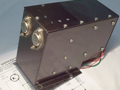
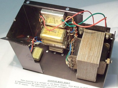
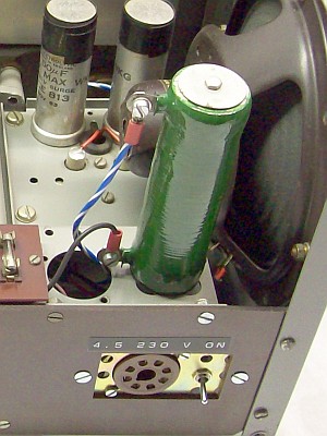
This unit is model 909A/2 that uses a transistorized power
supply (Pics #1 & 2) fitted internally to allow direct operation from a 24/28 VDC ship line voltage
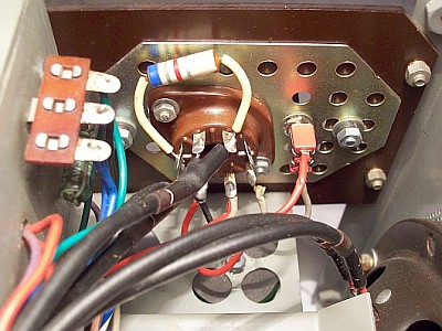
source. For home use the radio was restored to the standard model 909A by removing
this power supply, also the 8-way Alpha connector was replaced
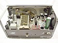
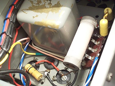
by a normalized octal connector and a power switch installed aside (pic #3 and #5). Filaments are
connected in series via the voltage link board of the radio, voltage to filaments is reduced by means of
a 968 ohm ballast resistor (pic #3). HT voltage is obtained directly from the 230
VAC mains, a silicon diode followed by a 68 ohm resistor (pic #4) reduces B+
voltage to about 250 VDC at the input of the smoothing filter, giving
230 VDC at the output, also this resistor protects the rectifier diode of the
input electrolytic capacitor peak charge. A 100 Kohm
load resistor (pic #4) was added to provide a fixed load in order to
control the peak voltage accumulated into the output electrolytic
capacitor while filaments are still cold. Two leaky paper capacitors
were replaced. The receiver manages very well voltages from 220 to 240
VAC, and this restores the 909A standard AC/DC mains system without voltage
selector, useless nowadays.
This receiver is now back to life, but its usefulness is minimal, it is a simple AM receiver of the old marine frequencies for fishing boats equipped with a cristal filter and noise limiter to be used mainly on MCW (CW code tones AM modulated) and phone communications. For collectors only, but it is very interesting to analyze its circuital design because of the way in which the band filter systems have been added, both in the front-end and in the intermediate frequency, very straightforward. And like all the classic Eddystone models, bomb-proof construction, you will never see this type of construction again.
 |