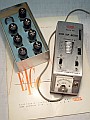
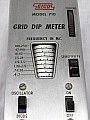
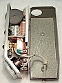
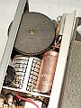
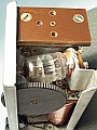
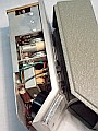
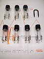
Using the Eico 710...
As Grid-Dip Oscillator: Used to determine
the resonant frequency of a de-energized RF circuit or an LC self-resonant
component, power to the RF circuit in question must be turned off before
making the test. The probe coil covering the expected frequency range is
plugged into the coil socket and the OSCILLATOR-DIODE switch is thrown
to OSCILLATOR. The 710 then becomes a VFO with a DC meter in the grid return
circuit that indicates the level of "environmental" power radiation produced
by the oscillator. Set the SENSITIVITY control for a mid-scale reading
on the meter at center of the frequency range, the "probe" coil must be
located close the circuit to be analyzed, turn the TUNING control until
a sudden drop in meter reading is produced, the "dip", it reveals the resonant
frequency that matches with the resonant frequency of the target circuit,
this is so because the power it absorbs. The frequency dial setting for
the particular coil used at the lowest point of the dip indicates the resonant
frecuency of the circuit under investigation, and a more or less sharp
dip will occur depending on the circuit Q. A point worthy of note regarding
this is that reading accuracy depends on the measuring distance: With the
probe-coil located very close to the LC circuit a less precision will
be obtained, conversely, moving away the coil a better precision is obtained,
but the radiation produced by the GDO may be insufficient for a good "dip"
reading.
As Wavemeter (field strength meter): Used to determine
the frequency and power level of an energized RF circuit. The probe-coil
covering the expected range is plugged into the coil socket and the OSCILLATOR-DIODE
switch is thrown to DIODE. The 710 then becomes a tuned RF diode detector
or absorption-type frequency meter. The instrument meter is effectively
in the diode load circuit and will read increasingly up-scale as the TUNING
control is turned to the vicinity of the RF source, read the frequency
dial setting for the particular probe-coil used at the maximum meter reading
on-scale.
As Zero-Beat Detector: This is a more sensitive method
used to determine the frequency of a RF source. The probe-coil covering
the expected frequency range is plugged into the coil socket and the OSCILLATOR-DIODE
swich is thrown to OSCILLATOR. A high impedance magnetic headphone is plugged
into the PHONE jack which automatically cuts out the instrument meter.
When the energized probe-coil is suitably coupled to the energized unknown
RF source. The unknown RF energy picked up mixes with the known RF energy
provided by the probe-coil, a difference frequency equal to the difference
between both frequencies is developed in the mixing (heterodyned) and is
called the "beat" frequency. When the difference is very small the "beat"
frequency falls into the audible range and can be heard in the headphone
as a whistle, the lowest pitched whistle (lowest tone) corresponds to the
frequency coincidence and is called "zero-beat", meaning zero difference
frequency. Note that at high frequencies, the entire audible range is such
a small fraction of the frequency in question, hence the "zero-beat" will
be heard simply as a "click" in passing through coincidence.
As Signal Generator: Use the 710 as Grid-Dip Oscillator.
Mounting the coil that covers the desired frequency range, the 710 can
be used as an RF generator or a signal marker generator when it is loosely
coupled to the input step of a circuit, or the antenna cable of a receiver.
As Capacitance Meter: Capacity measurement within 50 pF
and 5,000 (50 µµF to 5,000 µµF) pf is available
with the 710 translating "dip" frequency measurement to a grap for to convert
frequency to picoFarads (micro-microFarads) depending on coil mounted.
The method is to connect the unknown capacitor across the F coil to create
a resonant circuit. The 710 is then used as Grid-Dip Oscillator with the
C, D, or E coil plugged-in depending on the estimated capacity to determine
the resonant frequency. From the resonant frequency, the unknown capacity
can be obtained from this graph.
As Inductance Meter: To measure the inductance of a coil
connect across it a 100 pF capacitor. Using the 710 as Grid-Dip Oscillator
couple the probe-coil to the unknown coil and determine the resonant frequency.
The unknown coil inductance "L" can be found from this formula: L (henries)
= 1 / 39.48 x f2 (cicles) x C (farads).
As Q meter: To measure the Q of a resonant circuit use
the 710 as a signal generator. Connect a VTVM with a RF probe across the
circuit in question, couple the probe-coil to the coil in the resonant
circuit and find the resonant frequency wich should correspond to a maximum
or peak voltage reading on the VTVM. Note the resonant frequency f0.
Then shift the 710 frequency on both sides of resonance to points where
the VTVM voltage reading is about 70.7% (3 db down) of the maximum voltage
reading noted at resonance. Note the frequencies f1 and f2 at which
these voltage readings occur. The value of Q can be found from the following
formula: Q = f0 (center frequency) / f1 - f2 (side frequencies where the
response is 3db down).
As Quartz Xtal Checker: Use the 710 as Grid-Dip Oscillator
using the coil that has in its range the frequency labeled on the crystal
to be tested. Connect a short lead with an alligator clip at each end across
the crystal holder pin making a loop. Insert the probe-coil into the loop
and tune for grid-dip indication; the crystal frequency can then be read
from the intrument's frequency scales. This check also indicates the activity
of the crystal, an inactive crystal will not produce grid-dip indication.
As Parasitic Oscillation Sniffer: Use the 710 as Zero-Beat
Detector. With power applied to transmitter, listen on headphone while
varying the operating frecuency of the 710 fo a beat indicating the presence
of a parasitic oscillation. If it is found read its frequency from the
710 scale and remove power from the transmitter. Use the 710 as Grid-Dip
Oscillator to find the circuit or component resonant at the parasitic frequency.
Pre-setting transmitter tuned circuits: Remove plate power
from transmitter but leave all tube in the sockets and all circuits completed.
Proceed to adjust tank circuits to desired frequency, after which plate
power may be applied and final adjustments of alignment can be made with
grid and plate meter indications. Connecting the 710 as a Wavemeter, each
tank may be checked for correct frequency beating using the zero-beat detection,
but the increased sensitivity makes it necessary to avoid mistaking beats
with other energized RF circuits. Also, beating against harmonics may occur;
the lowest frequency beat heard is the fundamental.
Neutralizing stages: Remove plate power from the stage
to be neutralized (power to the driving stage and filament power should
remain applied). Two methods:
-
Use the 710 as Wavemeter: Couple the 710 probe-coil to the output tank
to the stage being neutralized. Set the 710 to the driving frequency and
check for the presence of RF in the output tank circuit as evidenced by
some meter reading other than zero. If RF is present, adjust the neutralizing
capacitor until the meter reading goes to zero.
-
Use the 710 as Grid-Dip Oscillator: Couple the 710 probe-coil to the grid
tank of the stage to be neutralized with the meter set to the bottom of
the "dip". The 710 meter reading should remain unaffected as the plate
tank capacitor is varied if neutralization has been achieved.
Antenna adjustments: The 710 used as Grid-Dip Oscillator
aids in the adjustment of antennas without causing interference. The antenna
should always be near its final height and position if the resonance readings
are to have real value. In any case, the proper type of coupling should
be used (inductive at currents maximums, capacitive at voltage maximums)
and this coupling should usually be loose. Coupling along the line or at
end is possible with parallel feed lines, but a coaxial line can only be
coupled to at the ends. Checking at the end of a line is usually done by
inductive coupling to a shorting loop across the inner and outer conductors
od the coaxial cable or across the ends od the parallel feeders. Correct
matching of open wire lines to an antenna can be checked by using the 710
as Wavemeter to indicate the presence of standing waves, power must be
fed into the feed lines by the transmitter, the probe-coil must be moved
along the line with constant coupling maintained and watching over considerable
variations in readings. When correct matching of the line is obtained standing
waves will disappear. To analyze correct matching of a coaxial line place
the 710 near the antenna using the instrument as a field-strength meter,
maximum meter indication indicates the actual output from the antenna.
Receiver tuned circuits adjustment: Use the 710 as Grid-Dip
Oscillator. With receiver power off adjust each circuit to the desired
frequency, gang-tuned circuits should be checked at both ends of the range
and a few points in between. After that apply power to the receiver and
use the 710 as a Signal generator to check the final alignment. Attach
a short cable into the antenna plug, tune the receiver with AVC on to a
frequency at which no signals are present, tune-in the 710 and observe
the S-meter, else a VTVM should be connected to the receiver detector or
the AVC line as an indicator. The local oscillator can be cheched using
the 710 as Wavemeter, couple the probe-coil to the receiver oscillator
coil; a maximum up-scale reading should be obtained at the resonant frequency
of the oscillator tank circuit if it is functioning. |