| The quality factor (or Q) of an inductor is the ratio of its inductive reactance to its resistance
at a given frequency, and is a measure of its efficiency. A Q-Meter consists internally of a calibrated VFO (variable-frequency oscillator) capable of inserting a known voltage in series with a resonant circuit, and a VTVM (vacuum-tube voltmeter) which measures the voltage across the resonant circuit. Q-Meter reading will be E/e, where e is the inserted voltage, and E is the voltage read by the voltmeter. By maintaining e constant, the voltmeter can be calibrated directly in Q values. The higher the Q factor of the inductor, the higher will be the gain, ability to oscilate,
and narrower the bandwidth in relationship to the central frequency. The QM-1 is designed to enable
technicians and experimenters to simulate conditions actually encountered
in practical circuits and measure the performance of the coil or condenser
by itsef. Such measurements are made at the operating frecuency actually
encountered in the practical circuits, and these measurements provide information
about the Q (quality) factor of the L/C (inductance/capacitance) tank at
selected frequencies. |
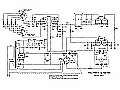
Heathkit model QM-1 construction details + Schematic & Operation
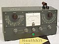 |
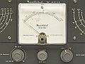 |
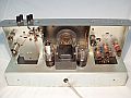 |
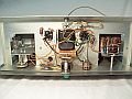 |
 |
 |
|
Specifications:
| FREQUENCY ranges |
A |
150 Kc to 480 Kc |
| |
B |
450 Kc to 1600 Kc |
| |
C |
1450 Kc to 5.4 Mc |
| |
D |
4.8 Mc to 18 Mc |
| RESONANCE scales |
Inductance L (dep. test freq.) |
1 µH to 10 mH |
| |
Capacity CE (effective) |
40 to 400 pF |
| |
Capacity CT (total) |
40 to 450 pF |
| VERNIER |
7 pF |
-3 pF to +3 pF |
| Q scale range |
Full scale X1 or X2 |
250 |
| Test coil specifications |
At 790 Kc (range B) |
L=250 µH
CE=96 pF
Q=110 |
Notes:
CE:
Effective capacity, the capacity of RESONANCE (this capacitance is in series
with the 5000 pF injection padder).
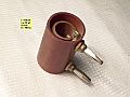
5000 pF injection padder: Special capacitor connected between one binding post "L"
and chassis, it is in series with the coil under test; the RESONANCE capacitor
is connected between the binding posts "C", one of them is common to the
other binding post "L", and the other is connected to chassis. This capacitor
is sandwich mica design with wide and very short leads in order to eliminate
any inductive reactances. There must be a circuit capable of resonance
and there must be a signal to which the circuit can resonate. The signal
is obtained from the generator section, and the resonant circuit comprises
the RESONANCE capacitor connected between the "C" binding posts, the injection
padder, and the coil under test. If the current flow from the generator
through the injection padder is obtained from a constant current source,
the voltage at resonance developed across the coil under test will be directly
proportional to the Q of the L/C tank at a given frequency. Because the
injection padder is much larger than the RESONANCE capacitor (450 pF),
practically all of the voltage across the coil appears across this capacitor,
where it is measured by the VTVM circuit.
CT: Total capacity, the capacity of the RESONANCE capacitor + the stray capacities
in the wiring.
Tubes: 12AT7 (oscillator), 6AL5 (VTVM diode), 12AU7 (VTVM amplifier), 6X5 (rectifier), & 0D3 (voltage
regulator).
SET LEVEL: This control injects
voltage to oscillator tube, the level of RF output is measured on the meter
when the CAL-Q switch is in CAL position, the X2 and X1 marks are measurement
basis, if this control is settled counterclockwise the oscillator will
not work due to lack of CC voltage, keep in mind this on frequency tests.
|
Practical uses:
To measure the
Q of a coil (use "L" binding posts):
- Set switch to CAL.
- Select RANGE and FREQUENCY to the
desired operating frequency.
- Adjust SET LEVEL to X1.
- Set switch to Q, make sure there
isn't any resonance at that point (tune off RESONANCE).
- Then turn SET ZERO for zero meter
reading.
- Adjust RESONANCE accurately for maximun
indication on the meter.
- Read the Q value on the meter. If
the meter reads off scale, switch to CAL and adjust SET LEVEL to X2, switch
to Q and double the indicated value.
- The indicated capacity on the C scale
is the capacity of resonance of the tested coil.
- Q and capacity values refers to the
operating frequency, at other frequencies Q and capacity will have other
values.
To measure inductance
of a coil (use "L" binding posts):
- Set switch to CAL.
- Select RANGE and FREQUENCY to
operating frequency of 250 Kc, 790 Kc, 2.5 Mc, or 7.9 Mc.
- Adjust SET LEVEL to X1.
- Set switch to Q, make sure there
isn't any resonance at that point (tune off RESONANCE).
- Then turn SET ZERO for zero meter
reading.
- Adjust RESONANCE accurately for maximun
indication on the meter.
- Read the inductance on the L scale.
- Place the decimal point properly
by referring to the frequency-inductance tabulation. Use "L" scale with
frequency set to:
| 250 Kc |
1 - 10 mH |
| 790 Kc |
100 - 1000 µH (1 mH) |
| 2.5 Mc |
10 - 100 µH |
| 7.9 Mc |
1 - 10 µH |
|

|
