Capacitor issues on Collins 75A-4 receivers
The usual and the surprise.
There is a lot of scattered info on the Internet on recapping the 75A-4. There is a '7 Deadly Caps list', all mica except one ceramic, all of them are coupling capacitors. Coupling capacitors are the easiest to test, can be tested in-circuit and then act accordingly, they don't need to be removed if pass the test. But the capacitors that fail the most in vintage equipment are the so-called Bumble-Bees, the paper capacitors. There are also recommendations for replacing 75A-4's paper capacitors, a very common one is to extend the voltage of the new ones from 400 to 600 volts... in a receiver whose max DC voltage is 210 volts!!! My recommendation is to go in the opposite direction; in short, everything is a bit confusing, so this page is made with the intention of avoiding clichés and carrying out tests that provide, IMHO, concrete evidence and focused info.
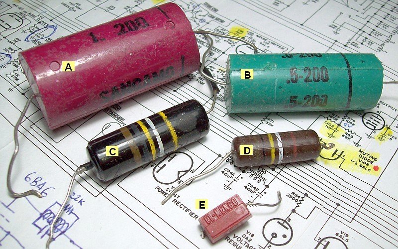
— Problematic capacitor types in the 75A-4: Paper is the usual, mica is the surprise, well, in fact silver mica, maybe that's where the problem is (IMO faulty manufacturing by EL-MENCO, see pic below). Standard mica and ceramic types usually don't fail, and the electrolytic ones can be easily reformed (polarized) if they are not dry or fatigued by power surges —
- ) Sangamo 1 µF 200 volts, waxed paper C-102.
- ) Sangamo .5 µF 200 volts, waxed paper C-124.
- ) Sprague Bumble Bee .1 µF 400 volts, PIO, C-20, C-62, C-70, C-97, C-98, C-108, C-111, C-112, C-115, C-116, C-146.
- ) Sprague Bumble Bee .1 µF-150/200 volts, waxed paper, C-54.
- ) EL-MENCO capacitor, sealed silver mica, 60 units of various values.
Is something usual missing? The electrolytic ones (that appear recurrently in recapping lists) are usually NOT problematic(*), and even less so in the 75A-4, since this receiver works with a relatively low B+ (another surprise) and has tube rectification. What can happen is that the electrolytics become depolarized due years without use, but since they are of quality and have not suffered surges all are fully recoverable. In the case of the 75A-4, I seriously doubt that it is necessary to replace the PS filter capacitor unless someone has previously damaged it by not having the patience to carry out the appropriate protocol before plugging it in again. Refer to the text at the bottom for the exact PS electrolytic filter capacitor reforming -polarization- procedure that has been performed on this 75A-4.
|
PAPER CAPACITORS (13+1), the easy part (up to some extent).
| ITEM |
CIRCUIT FUNCTION |
VALUE-VOLTAGE |
OPERATING VOLTAGE |
COMMENT |
NEW COMPONENT |
| C-20 |
AVC line, V-2 Grid decoupling |
0.1 µF-400 |
-1/-35 |
-35 GAIN to max. Why 400? |
0.1 µF-100/160 |
| C-54 |
V-6 Cathode bypass 1 |
0.1 µF-150/200 |
0/+8 |
100 is enough |
0.1 µF-100/160 |
| C-62 |
V-5 Plate decoupling |
0.1 µF-400 |
170 |
OK |
0.1 µF-400 |
| C-70 |
V-7 Plate bypass |
0.1 µF-400 |
175 |
OK |
0.1 µF-400 |
| C-97 |
V-12 NL Cat-decoup 2 / bypass 3 |
0.1 µF-400 |
-30/+2 |
NL MIN/MAX. Why 400? |
0.1 µF-100/160 |
| C-98 |
V-12 NL Plate decoupler |
0.1 µF-400 |
-65 |
NL OFF position. Why 400? |
0.1 µF-100/160 |
| C-102 |
V-22 Grid decoupling 4 |
1 µF-200 |
-10 |
100 is enough |
1 µF-100 |
| C-108 |
AVC amp NL V-16 Cathode BIAS |
0.1 µF-400 |
+15 |
B+ divider, 400 volts is OK. |
0.1 µF-400 |
| C-111 |
AVC amp NL V-16 Plate bypass |
0.1 µF-400 |
-1/-30 |
-30 GAIN to min. Why 400? |
0.1 µF-100/160 |
| C-112 |
AVC circuit time constant |
0.1 µF-400 |
-1/-30 |
-30 GAIN to min. Why 400? |
0.1 µF-100/160 |
| C-115 |
BIAS bypass |
0.1 µF-400 |
-30 |
Why 400? |
0.1 µF-100/160 |
| C-116 |
V-18 VR Anode bypass |
0.1 µF-400 |
148 |
VR tube B+ line, OK. |
0.1 µF-400 |
| C-124 |
V-22 Screen Grid bypass 4 |
0.5 µF-200 |
175 |
200 volt is a bit short |
0.5 µF-400 |
| C-146 |
V-12 Noise Limiter, filter 3 |
0.1 µF-400 |
untested |
NL version SB-2, ONLY |
0.1 µF-100/160 |
— C-146 only exists in SN 2716 and higher (SN of this unit is about 200 lower).
— It is not worth taking up more space using capacitors with voltage rating well above the particular needs of the circuit, what matters is the quality, the specification voltage must have enough margin with the operating voltage, that's all. There are 10 original 400 volt capacitors, that are reduced to 4, only 1 of 200 volts, which is increased to 400, thus giving a total of 5 of 13.
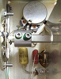
- ) Located inside a narrow and crowded area, at pin 7 of V6. Very hard to remove, the new one is located connected to the variable adjust lug of R9, IF GAIN ADJUST pot (which is also connected to pin 7, see below for more info on this).
- ) Original Noise Limiter; 75A-4 receivers below SN 2716.
- ) 75A-4 receivers SN 2716 and up. Noise Limiter Service Bulletin 2; trying to manage noise pulses. Update not included due to doubt about the real effect of the modification (original design is not perfect but very effective). Noise limiters never worked as expected, and usually, when they try to solve noise they make distortion worse.
- ) Sangamo capacitor, paper (see pic above), but still VERY usable after almost 70 years unlike the Bumble Bee Spragues (all destroyed). Changed with a modern capacitor to clear circuit area, not because it failed.
These capacitors have a very high probability of leaking at all or almost all of them. Performance reports for a 75A-4 are only correct when there are no leaks in its capacitors, and audio reports only when the SSB system is correctly adjusted. Leakage is the main reason for replacement, but an additional reason is that these capacitors are big, and take up a lot of space in the circuit. By doing so, everything looks 'cleaner'. I recommend using the values above on the right to save space in the circuit and money in your pocket. Prioritize 'mustard' (axial) type capacitors if you want to follow the classic line (like most that I use), although for certain substitutions the printed circuit type (Orange-Drop and similars) are better. I like to select each type of capacitor for each circuit application.
Summarizing: It can be considered very seriously that all of them should be replaced by others with plastic dielectrics.
|
|
SILVER MICA CAPACITORS (60), the intricate part (a possible 75A-4s' hidden nightmare).
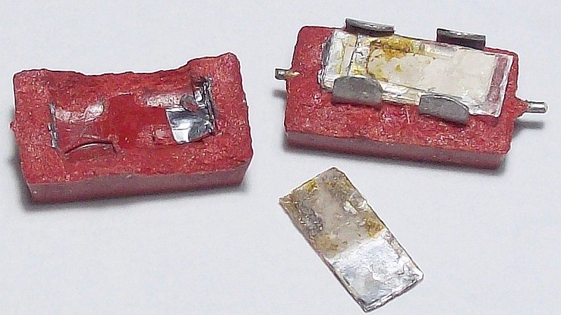
75A-4's leaking silver mica capacitor example — A component should not be replaced by assumptions, but by tests and evidence —
|
Why does a completely sealed capacitor, without cracks (paper Bumble Bees and Black Beauties usually have them), have this internal failure? Note the black outline of the silver and a yellowish spot on the dielectric, the capacitor must withstand 500 volts, the maximum voltage of the 75A-4 reaches only 200, so so the voltage should not be the cause of the failure. Mica is very resistant to impregnation, silver only 'oxidizes' when exposed. IMO if these capacitors are leaking it must be due to some contamination in their manufacturing process that has worsened over time.
→ How to test coupling capacitors in-circuit? Coupling capacitors are the ones that follow the signal from one step to the next, usually from an output plate to an input grid. The plate always has a positive potential, usually high, and the grid usually has only the bias voltage, normally very low and always negative with regard to the cathode. The test setup could not be simpler, it consists of detecting if the grid
has positive voltage, if there is, it comes from the plate due to leakage within the coupling capacitor. This test must be carried out after a while of operation (more on this below). Steps are:
- ) Use a DVM (or VTVM), red wire is positive, black wire is negative or ground, schematic aside.
- ) Locate on the schematic a capacitor that goes from the plate of one tube to the grid of the next (output/input).
- ) Confirm the existence of positive voltage on the plate of the output tube. Black tip to ground and red tip on the pin of the tube
socket that corresponds to the plate.
- ) Change the red tip to the pin of the socket that corresponds to the grid of the input tube. If the voltage is zero or negative, the coupling capacitor is OK, confirm this by selecting a low scale on the DVM. If positive, the capacitor is leaking.
- ) Control grid DC voltages (polarization) can be accurately tested by placing the red tip on the grid pin, and the black tip on the cathode pin, use a low scale. The reading should be negative or zero.
Since the AVC (AGC) injects negative voltage into the control grids of the tubes included in the AVC line, it is advisable to set the AVC switch to OFF to eliminate any negative voltage that neutralizes the positive leakage voltage, thus mistakenly accepting a defective capacitor. Also RF GAIN should be set to max.
Mica capacitors associated with coils may be affected, many of those capacitors do not handle B+ voltage, only AC signal, but if the quality has degraded these capacitors will not do its job properly. Also capacitors associated to the tuning range (padders like C-24) may be affected, the value os these capacitors is very important because the permeability tuning core (1 inch long) should run almost centered on the total coil turns when the dial indicates the lowest frequency, and almost off the coil turns when the dial indicates the highest frequency (it must not lose tune at the end). If one of these padders fails and its value is non-standard, the correct value must be found using two standard capacitors and then adapt the set to the circuit (see pic below). C-24 does not appear in the usual replacement lists, which shows that making lists of 75A-4 capacitors for mandatory replacement does not make much sense, since any mica can fail, what we have to do is have procedures to check them.
→ How to spot bad mica tuning capacitors? If a slug adjustment progresses very slowly and shows a very gentle peak, it can be surely assumed that the associated tuning capacitor is defective. The same applies when the tuned frequency suddenly makes strange changes. The most obvious evidence of a defective EL-MENCO silver mica capacitor is capacity fluttering, which is combined with leakage. A defective capacitor causes the affected band to have much less sensitivity due to low Q.
The coding system for these capacitors is not common, see the correspondences below. Hover over the graph below to see one of these problematic mica capacitors.
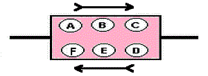
A
Class ID
color |
B
First figure
color |
C
Second figure
color |
D
Zeros after
C |
E
Tolerance
color |
F
Characteristic
ppmºC / drift |
White: EIA
Black: MIL |
Black...... 0 |
Black...... 0 |
Black... none |
None: 20%
Silver: 10%
Gold: 5% |
1000 / 5% |
| Brown.... 1 |
Brown.... 1 |
Brown.... 1 |
500 / 3% |
| Red......... 2 |
Red......... 2 |
Red......... 2 |
200 / .5% |
| Orange.. 3 |
Orange.. 3 |
Orange.. 3 |
100 / .3% |
| Yellow.... 4 |
Yellow.... 4 |
Yellow.... 4 |
-20 +100 / .1% |
| Green..... 5 |
Green..... 5 |
Green..... 5 |
0 +70 / .05% |
| Blue........ 6 |
Blue........ 6 |
Blue........ 6 |
|
| Violet..... 7 |
Violet..... 7 |
Violet..... 7 |
| Gray........ 8 |
Gray........ 8 |
Gray........ 8 |
| White..... 9 |
White..... 9 |
White..... 9 |
EL-MENCO silver mica capacitor code/specs. Max rating for DC working voltage is 500.
Correct decoding position: Subtle arrow in the middle of the colored dots facing right. |
The failure of the mica capacitors is a surprise, I've never found failure with mica capacitors, but they were standard, not silver mica (silver mica was initially designed as a special quality grade for critical tuning circuits). Perhaps here we have another example that the most advanced and modern can be a drawback later due to long-term side effects. Sixty capacitors are a lot, too many to change them all, not only because of the work, but also because of the damage that such extensive work causes to the circuit. When good soldering practices are used, everything from the old capacitor must be removed, this involves touch up welds that have leads "sewn" to the terminals and then tightened with pliers (a nightmare, surgical techniques are needed to set free those leads). Otherwise, on wanting to shorten the work, there is the risk that it will look like it was done by an electrician instead of by an electronics technician.
|
|
MICA CAPACITORS in this unit that have proven defective or leaky
| ITEM |
CIRCUIT FUNCTION |
VALUE-VOLTAGE |
OPERATING VOLTAGE |
PROBLEM |
REPLACED BY |
NEW COMPONENT |
| C-24 |
Padder tuning for L-6 (80m) |
650pF-500 |
165 |
Defective (1) |
Styroflex type |
650 pF-400 |
| C-68 |
V6 plate to V-7 grid coupler |
470pF-500 |
165 |
Leaky |
Ceramic tubular |
470 pF-400 |
| C-81 |
V-9 IF amp grid coupling |
470pF-500 |
165 |
Leaky |
Ceramic tubular |
470 pF-400 |
| C-104 |
V-21 AVC amp grid coupling |
470pF-500 |
165 |
Leaky |
Ceramic tubular |
470 pF-400 |
(1) Capacitance fluttering effect - 650 pF is a non-standard value, so this capacitor must be made with two in parallel, see pic. 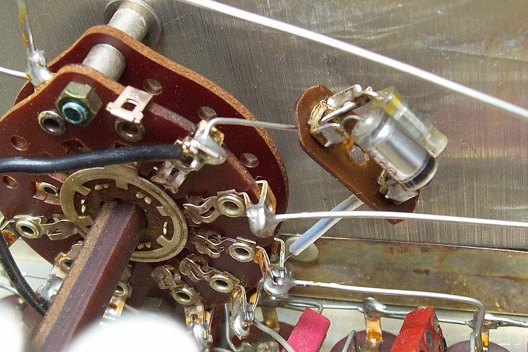 It may be interesting to make mica capacitor lists just to see which ones tend to be problematic, but there are 60 candidates!
| Coupling capacitors (plate to grid) in the 75A-4 are: C-19, C-34, C-38, C-52, C-144, C-68, C-71/C-75, C-81, C-95, C-100, C-101, C-205 (LO, V-14 and V-15 tubes need to be pulled out, V-14 is a pentode but works as a triode, test is made via the socket pins), C-104 (AVC amp). There are about 60 mica capacitors in a 75A-4 (micas C-147 and C-148 are part of the NL SB-2 version). The mica lists found in the Internet mention only the most common ones to fail, but any of the 60 could fail, in fact, none of them should fail because none of them are under any particular stress, they are all sealed and 500 volts, the highest voltage applied to them does not reach 200 volts, thus IMO those that don't test leaky don't need to be replaced, in fact all the 60 mica caps are under suspicion, the hope is that defective ones will be the exception, not the rule; theoretically all of them should be replaced.
 Leakage in C-81 has a very pronounced effect on the 75A-4's performance. Some of these micas have leaks from the moment the 75A-4 is plugged in, but others do not, it is after a while when the leak begins to develop. It starts slowly at just .01 positive, having a final rapid period from .1 to 2 volts, the effect is a loss of gain clearly evidenced by a drop in audio level, first slow and then sudden. So anyone who experiences that variation already knows what is causing the problem. C-68, C-81, and C-104, were replaced by tubular ceramics because their length adapts very well to their respective connection in each location, but any other ceramic type, or styroflex, can be used. Leakage in C-81 has a very pronounced effect on the 75A-4's performance. Some of these micas have leaks from the moment the 75A-4 is plugged in, but others do not, it is after a while when the leak begins to develop. It starts slowly at just .01 positive, having a final rapid period from .1 to 2 volts, the effect is a loss of gain clearly evidenced by a drop in audio level, first slow and then sudden. So anyone who experiences that variation already knows what is causing the problem. C-68, C-81, and C-104, were replaced by tubular ceramics because their length adapts very well to their respective connection in each location, but any other ceramic type, or styroflex, can be used.
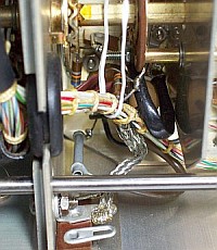 C-68, like C-54, is located within a crowded area (pic at right, see the new C-68), it takes patience and good procedure to replace it, it was necessary to pull up the wiring harness with a rope to access, as shown in the pic. The original C-54 (paper) is located even further inwards; therefore, once the original is removed, the new C-54 is installed near R9, IF GAIN ADJUST (pic above left). C-68, like C-54, is located within a crowded area (pic at right, see the new C-68), it takes patience and good procedure to replace it, it was necessary to pull up the wiring harness with a rope to access, as shown in the pic. The original C-54 (paper) is located even further inwards; therefore, once the original is removed, the new C-54 is installed near R9, IF GAIN ADJUST (pic above left).
Intrigued by these micas, an in-depth test was performed using the C-3. This test consists not only on verifying the voltages that the capacitor withstands but also on verifying these voltages during an entire test period, by doing this we get closer to the real operation in the circuit. Precisely those capacitors that gave a positive grid when tested with a voltage pulse gave correct test, but increasing the voltage in steps and holding it for a while revealed the fault: C-3's magic eye fluttering shows intermittent leakage, which depends on the voltage level applied. All three leaky capacitors gave a positive grid when tested in-circuit and, depending on the test voltage selected, flutter effect and leakage when tested with the C-3. The C24 defective capacitor had capacity fluttering effect, that is, a capacitor changes capacity randomly. Another interesting "property" of these bad mica capacitors is that once they have been out of circuit for a while (i.e. in a "cold" state), they test OK when checked again.
Summarizing: The main problem that arises in this receiver is the 60 suspected mica capacitors, if one fails any other can do the same, but on the other hand if the remaining ones have not failed in many years, they should not fail in the near future. This latent problem opens the door to unpredictable consequences, that's why the in-depth test has been carried out. I am afraid that, as the 75A-4 is used, new defective micas will appear. IMO all 75A-4's EL-MENCO have the potential to cause problems.
|
|
ELECTROLYTIC CAPACITORS: If they are not dry (AC hum) or damaged by overvoltage (hum + heating), they are all recoverable.
|
Reforming (polarization) of electrolytic capacitors in-circuit. The following steps define exactly what was happening in this receiver and what was done to fully recover the filter capacitor and therefore the rest of the electrolytics.
- ) It is necessary to have a method that lowers the mains voltage. I don't even have a variac, but carrying out this procedure with a variac is very useful. Any procedure to bring the 75A-4 into contact with half the current mains voltage works, for example a step down transformer, in my case from 230 volts (EU) to 115 (US) but... the 75A-4 is 115 volts only!!! So I am forced to connect two 230-115 transformers in-line to obtain 115/2, half the 75A-4 mains voltage, this is, 230→115 and the other would be 115→58. The 75A-4 can be left connected like this for 1 hour; the voltage is so low that it is impossible for anything to happen. This serves to make the electrolytic capacitors "wake up", the entire device "operates" at medium voltage. This step should always be carried out when you have an unknown old device in front of you, whether modern or old electronics.
- ) The next step is to enter the "hot phase", which is what was done in this case but an intermediate step may be necessary, and that's where the variac is useful. You have to be able to touch the filter capacitor, which is very easy in the 75A-4. I turned on the 75A-4 to 115 VAC for 10 seconds and then turned off. Normally the capacitor stays cold and nothing happens. Reconnect for 30 seconds and disconnect. If everything remains the same, it is possible to connect for 3 minutes, the capacitor will start to heat up clearly if it is leaky (which happened), power off. Wait for it to cool and power on for 5 minutes, normally the heating will be about the same as at 3 (which happened), this indicates the PS filter capacitor is already recovering a bit. A 5-minute session is repeated again, the 75A-4 is turned off and allowed to cool for half an hour.
- ) After the capacitor is completely cold repeat a 5-minute session again. If after 5 minutes it heats up moderately, continue up to 10, and then turn off the 75A-4. After 10 the capacitor will be somewhat hot, this is normal. Let 15 minutes pass. The name of the game is the capacitor increases its internal resistance through polarization, when this happens it get less hot.
- ) Now it can be connected without having a specific test time, the moment in which the device is disconnected will depend on the
heating level of the capacitor, but the session should not exceed about 15-20 minutes. After this session, the 75A-4 must be allowed to cool completely.
- ) At this time the triple filter capacitor (3x40 µF/300V) is already half reformed, but it still cannot be turned on for 1 hour, for example, during that time the temperature of the capacitor would rise excessively. Now the procedure is based on "QSO sessions", several times. In the last one it will be verified that the capacitor is heated more by the environment and less by itself (keep in mind that all electrolytics tend to heat up to a certain degree due to operation, this is provided for by design).
- ) After a few sessions, and letting the receiver cool, it is turned on again. To your surprise you will find that the capacitor hardly gets hot, it barely gets hotter than the surroundings. Right now it's about using the 75A-4 normally but checking the filter capacitor from time to time. By prolonging use, if the self-heating of the condenser does not increase, it is already completely reformed. The PS electrolytic of this 75A-4 was recovered that way, the total process took about 12 sessions. The rest of the electrolytics follow automatically the same steps, monitorization on these is usually not needed, if they are not dry or fatigued by overvoltages they will reform at the same time. Now, with the 75A-4 plugged in for hours, this capacitor does not get hotter than the surroundings, no AC hum, and full B+.
|
This may seem like grandma's method, but it works perfectly. With this procedure is not necessary to compromise the aesthetics of the circuit or spend money, you just need to have an interest in electronics and a little patience. This procedure has been successfully applied to all types of old electronic devices, including transceivers (see the HW-101 page). No AC hum or endless electrolytic capacitor heating, but it is very important that no previous owner has operated the device irresponsibly (keep it on for a long time the first time). Note that if the indicated steps are not followed, it is the user himself who damages the capacitor at that moment, not because it was previously damaged.
Whether an electrolytic capacitor is old has nothing to do with whether it can be reused or not. This capacitor is almost 70 years old, if the
tightness is maintained (it has not dried out), and if it has not been "mistreated", it will be recovered without problem regardless of its age, as demonstrated.
Summarizing: Electrolytic capacitors should never be replaced out of habit, they must be checked and it is not difficult to do so. Most of the time installing new ones will do no good, especially in receivers; much better is to reform them. When it only happens that they have not been used for a long time, it is not difficult to do so.
(*) The reputation of electrolytic capacitors as a problem comes out from the usual professional action on them, 'replace all by default'. The reform procedure takes time, and since complete success cannot be guaranteed, the simplest thing is to replace the component. This has given way to the cliché of mandatory replacement, and this cliché has been repeated ad nauseam without checking its validity. With the enormous change that the components have undergone (size and planned obsolescence), the option of throwing away the old one and replacing it with a new one is no longer so advantageous, the appearance of the old device is greatly compromised, and in some cases where the aesthetics of the old capacitor (surface mount) are taken into account, it is doubtful that the new component inside (unknown manufacturer in many cases, therefore dubious quality) performs better than the old one once reformed.
|
|

|