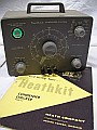
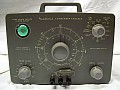
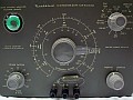
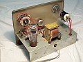
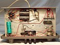
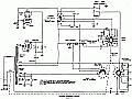
| The Heathkit C-3 Condenser Checker is
an instrument that allow us to measure capacity, resistance, AND its most
important function which still makes it useful nowadays, since no modern
equipment provides us with it: Capability to detect leakage in the old
paper and electrolytic capacitors that are present in 40's, 50's, and 60's
radio and audio equipment, in order to avoid making a complete recapping,
saving money, some work as well, and the MOST important, respecting the
original circuit appearance. IMO, an old boatanchor totally refurbished
with printed-circuit components becomes absolutely depersonalized. It also
measures the Power Factor of electrolytic capacitors, ESR measurement
in "modern language".
Since 1961 the C-3 has one successor with different shape
and much more switch-selected leakage voltages: The IT-11, which has a
more complicated design. Its name was changed to "IT-28" in 1968; same
model with different painting (simple appearance), lower quality knobs,
but 115/230VAC compatibility, which is best for worldwide users. If your focus
is on tube rigs, the extra ranges provided with these last two models (voltages
for transistor components and a more graduated high range) are not needed.
The C-3 is very easy to use and it will be the best choice. This unit is
ideal for testing capacitors used in "boatanchors", giving both an accurate
reading for capacitance in addition to the ability to test for leakage
at a range of switch-selected voltages until 450 volts. The leakage detector
switch is spring loaded so as soon as you let go it springs back to empty
the test charge in the capacitor under test, eliminating the risk of shock
from charging up a capacitor once it has been checked, so you know that
the caps are going to operate well under the high voltage loads used in
tube circuits. Modern multimeters and the like are not capable of telling
you this information. A neat design with great flexibility.
Using the C-3 we can do the following:
- Check resistor values.
- Check capacity in all types of capacitors and open/short condition.
- Test leakage in all types of capacitors and charge time.
- Prepare stocked electrolytic capacitors for current use (new or not, but unused for years).
- Test electrolytic capacitors for quality and safe usage.
The last three applications are still very useful. |
Using the Heathkit C-3 Condenser Checker.
This instrument is not an "in-circuit" checker. An in-circuit
checker does not provide the leakage test feature, only provides a good/no-good
operation as the Heathkit models C-1, IT-22,
but these models can provide a "clue" about some possible leakage (partial
eye opening on the short test). Alternatively the Eico
955, which is a more sophisticated model and perhaps a bit more complicated
to use due the added ability to measure capacity in-circuit (but within
a limited range). The Eico does not provide any "clue" about some possible
leakage due the low testing voltage (6 volt), a leaky capacitor will be
considered good unless the leakage was very high (practically shorted).
Obviously, under normal use, at least one end of the capacitor
to be tested must be disconnected, but the operation may be complementary
to the use of the other instruments mentioned.
Operation is simple, and consists in to connect the test
leads to "RES" or "CAP" binding posts (center is POSITIVE and is common
to all testings).
- Resistance measurements are read directly on the outer scale when
the switch is set at the "R" position. When the switch is set at "Rx100",
it is merely necessary to add two zeros to the resistance measurement obtained.
- Capacitance measurements are reflected on 4 ranges, one inner scale
marked with 3 equivalent marks and another scale labeled "extended range"
located in the extreme inner portion of the dial calibration. On electrolytics
the Power Factor control must be set ON, this control only works on the
high and the extended range (last two capacity ranges).
- Leakage measurement is accomplished by selecting the voltage desired
on LEAKAGE TEST and rotating the other switch to the LEAKAGE position.
When this switch returns to NORMAL the capacitor tested is automatically
discharged via the 2K resistor used for the "R" scale, this provides a
quick and smooth discharge.
When a resistor or capacitor is connected in the correspondent
binding posts, the presence of a matched value is indicated by an increase
in the shadow angle of the indicator tube, and the presence of leakage
is indicated by a decrease in the shadow angle. Calibration is also easy,
it consists simply in to connect in its respective binding posts a calibrated
resistor/capacitor that matches a center dial value and loose/fasten the
knob setscrew positioning it in a correct dial reading.
|
Ranges, Inputs and Operation
| Leakage test at... |
25 - 150 - 250 - 350 - 450 VDC |
-Turn the main knob on the left *1.
-Use CAP binding posts, center is +.
-Select voltage.
-Rotate to LEAKAGE position.
-A totally open shadow indicates an EXCELLENT capacitor *2.
-A partially or totally closed shadow indicates a LEAKY capacitor *3. |
| Capacity test *5 |
0.00001 to 0.005 µF (10 pF to 5 KpF)
Low
*4
0.001 to 0.5 µF (1 KpF to 500
KpF) Med
0.1 to 50.0 µF (100
KpF to 50 µF) High
20.0 to 1000.0 µF (Extended Range) |
-Use CAP binding posts, center is +.
-Select range and rotate Main knob.
-A totally open shadow indicates its VALUE on the dial scale.
-A partially open shadow indicates a possible LOW QUALITY capacitor. |
| Resistance test *5 |
100 ohms to 50 Kohms
10 Kohms to 5 Mohms |
-Use RES binding posts.
-Select range and rotate Main knob.
-An open shadow indicates its VALUE on the dial scale. |
Power Factor control
(ESR measurement) |
This control only works in High
and Extended ranges.
When checking capacity or leakage of electrolytic capacitors, it
is essential that polarity be observed. These capacitors have a certain
amount of internal resistance IN SERIES with capacity. To balance the measuring
circuit, it is necessary to balance such resistance with a resistance in
series with the reference capacitor. This resistance is provided by the
Power Factor control, and is a measure of the energy loss in an imperfect
capacitor. The potentiometer scale (marked 0 to 50) indicates the loss
level, and this loss decreases the effective capacity measured. At maximum
power factor (50), the efective capacity is decreased to 87% of the measured
capacity. When measuring electrolytic capacitors, the Main control as well
as the Power Factor control should both be adjusted to sharp open indication.
This test serves the same purpose as a modern ESR (Equivalent Series
Resistance) meter. |
| Open Capacitor |
Is the capacitor which will not balance
on any of the ranges but allows the eye to open on the low end
of the
low-to-high ranges. |
| Shorted Capacitor |
Is the capacitor which will not balance
on any of the ranges but allows the eye to open on the high end
of all ranges. |
— *1 In order to avoid some sparks in terminals
5 and 7 (also 2) in the leakage switch. These sparks are caused by the
presence of the 0.250 µF capacitor.
— *2 Leakage is indicated by the degree of closure of the green electron
beam. When rotating the leakage switch and maintaining it on LEAKAGE position,
the eye tube will suffer a sudden closure and a return to normal shadow
opening immediately or after a second: This is the charge time,
and it is absolutely normal on the high ranges. It exposes the time that
the condenser needs to charge itself and depends on capacity. A partially
closed shadow or a fluttering condition would indicate a leaky capacitor.
If the eye closes entirely, the capacitor is shorted or the leakage at
selected voltage is high.
— *3 Comparing the eye aperture with the voltage selected we can know
the safe usage of an old electrolytic capacitor (maximum voltage
applied to safe operation, very interesting to filter capacitors). It's
interpretable, but a medium aperture would be OK. Totally open is excellent.
— *4 Direct connection on CAP bindig posts is strongly recommended; even
so, an inherent minimum capacity of about 5 pF will be added.
— *5 The effective test voltage applied
to the binding posts may vary from 1 up to 60 volts depending on value
of capacitor/resistor and range selected, therefore it is necessary to
bear in mind this if you try to check modern components. |
| PIOs, the Paper-In-Oil dielectric 'case':
It seems that the typical conclusion about the mandatory replacement of paper
capacitors should be revised. While there are some paper capacitors that die on
their own, even without being used, there are others that stand the test of time
very well, these are the paper-in-oil type (PIO) capacitors. PIOs have an outward
appearance similar to electrolytics, but they are not. These capacitors were relatively
not well known because its use was focused on military gear. The reason was that PIOs
support more voltage and capacity in smaller dimensions than wax-paper types. The surprise
is that many of these old PIOs perform very well when tested, so many times there is no need to replace them.
About 70 years ago, all paper capacitors were classified in the same "package",
but nowadays it is necessary to make distinctions, and also relate these
distinctions to the devices used for testing paper capacitors.
The C-3 does not distinguish between types of paper capacitors,
and the C-3 manual does not mention PIOs in any way. Usually PIO capacitors
weren't used as a default component, Heathkit did not use PIOs,
the manual refers to all of them as "paper", but the evidence is that the
dielectric type of paper in oil withstands aging much better than the
dielectric type of waxed paper. Tests carried out with C-3 show that capacitors
with capacitance less than 1 µF can be tested successfully in the
paper position (largest capacitances are an open topic for investigation). |
Common Doubts: Q & A's - Tips - Tricks - Mods
What is a leaky capacitor?
In few words, a capacitor shunted by an invisible resistor. The value
of this resistor varies depending on the effective DC current amount. This
variation is indirectly proportional: if DC increases, R decreases. A leaky
capacitor affects time-constant value and circuit isolation. The importance
of this affectance depends on the amount of leakage but, if the equivalent
resistance is high, the affectance is low. That is: Leaky capacitors
may work perfectly on one circuit and bad on another circuit depending
on the relationship between leakage and features of involved circuit.
At this point in time the original value of the capacitor is corrupted,
mutated to a variable value that depends on voltage and circuit specs. This
is easily detected by the capacitance tester circuit included in this instrument.
When a paper capacitor misses the original value shows on a lot of cases
a leakage clue; the capacitance shift is initially low, but when leakage
increases capacitance is seriously affected, capacitor becomes corrupted.
When a capacitor with great leakage drain is measured with this instrument
(bridge method) an erratic/undefined result is obtained, and when it is
checked on other instrument by the frequency method its meter shows a
surprisingly increased "capacity".
How to spot a leaky capacitor?
Checking operating voltages. Strange readings may detect the existence
of + DC in places where it must not have (i.e. tube grids) or its absence
in places where normally it must have (i.e. cathodes). A hot half-watt
resistor in the + DC line may detect the existence of a leaky decoupling
capacitor.
Using instruments like the IT-22
and interpreting the shadow gap in the eye tube.
When replacement is needed? (IMHO)
Mandatory:
- Tuned critical circuits (i.e. oscilators, measure bridges).
- Sensitive to bias circuits/components (i.e. power amps, HI-FI outputs,
mechanical filters, transistors).
- High voltage circuits (i.e. electrolytics in power supplies, bias
filters in oscilloscopes).
Recommended:
- Passive tuned circuits (i.e. IF's, filters, HI-FI compensating networks).
Optional: (if the leakage level is low/moderate).
- General low-profile circuitry (i.e. decoupling capacitors, pass capacitors
if the coupled circuit is not critical).
Is it possible to evaluate if the leakage is so significant?
As commented above, importance of leakage depends of the relationship
between shunt-resistance and features of associated circuit. The Condenser
Checker allow us "to calculate" this shunt-resistance by testing a capacitor
under several voltages. This instrument is very sensitive to leakage current
(too sensitive in my opinion). If the test on nominal voltage range is
OK (totally open shadow), capacitor is EXCELLENT. But... what about
a 400 VPP capacitor that shows totally open shadow in the 25 volt range
but it goes closing increasingly up to 350 volt range? Is it usable? To
determine that, I consider a "very acceptable capacitor" the one that has
an equivalent leakage greater than 10 Mohm, and a "questionable but still
usable capacitor", the one that has an equivalent leakage greater than
a 5.6 Mohm (measured at its NOMINAL VOLTAGE, at lower voltage the
leakage is significantly lower). These considerations applies to
non-electrolytics only.
- Connect a 10 Mohm resistor in series with an milliamperimeter (tester on
mA range) in the CAP binding posts, setting the voltage range to working
voltage. Power Factor OFF. Note the reading.
- Repeat the procedure with a 5.6 Mohm resistor.
- Repeat the procedure with the capacitor being tested; compare the readings.
If the reading of (3) is less than (1) the capacitor is "very usable". If it is
greater than (1) but less than (2) capacitor is "usable with care". If it
is greater than (2) the capacitor must be discarded.
Usually a capacitor with low to moderate leakage will work correctly
associated to low impedance components or in "low-profile" circuitry.
Broadly, paper capacitors greater than 0.1 µF must be replaced
both in high or low voltage circuits because large capacity paper capacitors
are more sensitive to leakage precisely due their higher capacity
(it has more waxed paper area susceptible to corruption).
From 0.01 to 0.1 µF it depends on voltage applied, and those within
the 0.001 to 0.10 µF range are perfectly usable unless some exceptions.
In case of not considering these thoughts a massive recapping should be performed,
this may be a lot of work, since all European equipment manufactured until early
60's and most American equipment manufactured until late 60's would need attention
(there are some exceptions, e.g. Hammarlund). This also creates another problem:
the "excessive-new" component along with the old one, a kind of "frankenstein circuit",
which it is clearly evidenced when solid-state circuitry is added to tube circuitry.
An example of these considerations: the C-3 itself.
- The 2 µF bridge capacitor (reference value for the bridge):
Leakage in this capacitor will cause bad readings. Same applies to the "20
Kpf capacitor" (2 x 10 Kpf). Replacement of both will be mandatory.
- The 0.25 µF decoupling capacitor included in the leakage test circuit:
This condenser can accept low leakage. A leaky capacitor in this
place will cause lower testing voltage. Capacity value may be affected
but it is not critical.
- The 0.01 µF coupling capacitor to 1629 grid: This condenser
can accept moderate leakage. A leaky capacitor in this place will
cause lower speed in eye opening. It works at low voltage; the leakage
at low voltages is generally low. Capacity value may be affected but it
is not critical.
Preparing a stored electrolytic capacitor to be used.
The procedure is: Power Factor ON and checking leakage by steps starting
from 25 volt up to nominal voltage of the capacitor and watching the eye
tube opening. If the eye opens totally, jump to next scale. Stop when the
eye starts to close totally. And now the most boring part... maintaining
the leakage knob turned ON for a while, watching the eye opening again...
(in order to avoid this, the return spring would have to be taken off,
but it is not reccommendable for checking under normal conditions). After
awhile the eye increases its opening... jump to next voltage range...
and repeat the same procedure until the eye is reasonably open at its nominal
voltage.
This procedure cannot recover the original value of a electrolytic
capacitor partially or totally dry, as it is not possible to recover,
only concerns regarding leakage. Therefore, it's always necessary to verify
capacity before the leak check. Fortunately, the C-3 allows that, and the
ability of capacity measurement built into the device is very useful. A
dry electrolytic capacitor will show an erratic behavior, no matched value
on its own range, and no logical balance on the rest of ranges.
Level of closure/aperture of the eye tube Mod:
The 1M resistor between pins 3 & 4 (plates) determines the limits
of closure/aperture of the eye tube. If the value of this resistor is too
low the eye will not open fully and it could strongly overlap when closed.
An increased value makes possible to adjust an adequate closure with moderate
overlapping or simply get the eye just closed when nothing is being measured. A 3M3 resistor would be a good candidate.
"25" Switch Position Mod:
The "25 volt" position for the leakage test is, in fact, a "40/45 volt
position" (Power Factor OFF/ON). This is a general factory issue of this
instrument, but... which is wrong? ... the labeled "25 V" mark or the internal
divider design? (45 volt seems best scaled to the next 150 volt position
than 25 volt considering voltages involved in tube circuitry and their
components). In order to create a true 25 volt position the last two resistors
on the low end of the voltage divider must be changed: 10k by 5K6, and
22K by 27K. If the test voltages for the rest of the positions needs to
be increased: 6K8 and 33K. Modifying the circuit the 25V range will be
implemented correctly, but if you consider 45 volt more useful than 25
volt (like me), delete and change "2" to "4" in the writing.
Voltage Balance Mod:
The 47 K resistor and the 22K-22K-22K-22K-10K resistors in series are
the main voltage divider: 47 K resistor applies for the 1629 tube (about
150V) and the "98 K resistor" applies for the leakage voltage selector
(about 450V). Aged components will cause modification of this balance.
If it happens, the 1629 will run too hot, or the leakage voltage selector
will be overcharged. Replacing this 47 K resistor makes possible to restore
original balance: If R increases, the voltage of the 1629 tube increases,
and the voltage of the voltage selector decreases; conversely if R decreases.
Tech Notes:
2 K res is associated to the R range. It also discharges
the capacitor just tested for leakage.
200 K res is associated to the Rx100 range.
200 pF cap mica is associated to the 10 pF - 5 KpF range
(Low range).
20K pF cap (two 10K in parallel) associated to the 1 Kpf - 500
KpF range (Medium Range).
2 µF cap is associated to the 100 KpF - 50 µF
range (High Range).
2 µF cap + 90 K res are associated to the 20 µF -
1000 µF range (Extended Range).
The transformer output voltage of 55 VAC applies to RC bridge measurements,
so it is not reccommended for measuring modern low voltage components.
The 500 VAC secondary applies to eye tube and the leakage voltage divider,
but note that there are models that this voltage is increased by about
50 volts. If this is the case, ensure that voltage of the electrolytic
filter capacitor associated to voltage divider is not exceeded. If it happens,
the value o the balancing 47 K resistor needs to be increased.
The output voltage available for each leakage switch position must be checked
in the CAP binding posts Power Factor ON (Electrolytic position).
The "leakage" of a 10 Mohm resistor is about 0.040 mA at 450 volt
range (Paper & Mica position).
The "leakage" of a 5.6 Mohm resistor is about 0.070 mA at 450 volt
range (Paper & Mica position).
The eye closes at about 0.010 mA of leakage.
Have been said that this instrument is too sensitive. On leakage tests,
the closure gap of the eye tube is controlled by the 470 K resistor. This
resistor is overpassed on Electrolytic position. Shunthing it by an adjustable
1 M resistor makes possible to set a precise closure gap for reference
purposes.
The eye increasingly closes when its grid (5) is more negative, then its
plate (3) become more positive.
The bright of the eye is associated to its plate voltage (+voltage, +bright).
This voltage is controlled by the 47 K resistor.
The 47 K resistor controls the balance of the main voltage divider. If
the voltage of the 1629 section is increased, the voltage of the leakage
switch section decreases.
Usual TLC:
- The 47 K resistor commented above may be replaced by another with
different value (usually greater).
- The 1 M resistor located between pins 3 & 4 may be replaced by
another with greater value.
- The 10 K & 22 K resistors present at the low end of the leakage
voltage divider must be replaced in order to match the front panel "25"
voltage position. Otherwise, you must consider this position as a "45 volt
position". Choose a lower value for the 10 K and greater for the 22 K.
- The "20 K capacitor" (two capacitors of 10 KpF in parallel) must
be replaced.
- The 2 µF capacitor must be replaced (usually with two of 1
µF in parallel).
- Cleaning, of course.
|
...\...
Vintage capacitors. A possible classification by type and level of damage; replacing criteria:
Destroyed: A capacitor that has completely lost capacitance and it is in fact a corrupted resistor (resistance varies depending on voltage applied and it also shows random capacitance). Many waxed paper capacitors fall into this category.
Leaky: A capacitor that totally or partially preserves its original capacitance, but gradually becomes to be a corrupted resistor. Depending on function and voltage that it handles in circuit can continue working. I'm afraid C-3 is not prepared for testing HIGH capacity PIOs, usually they tests leaky, optionally may be cheched like electrolytics (although they are not) accurately observing the charge and discharge effect on the magic eye.
Vintage: A capacitor that is old but well preserved. I'm referring especially to the mica ones, undamaged good quality PIOs, and by extension to other more modern ones such as ceramic and plastic with "mustard" lacquer, those can continue to work OK.
WP (Waxed Paper) type: The most problematic and doubtful. When tested in a Heathkit C-3, if at '25' volts (currently 40/45, more on this below) give total leakage (closed eye) must be discarded. When several close the magic eye at '25', all the rest of same capacity and manufacturer that are in-circuit must be discarded, since it is very doubtful that there are any good ones. If leakage is at higher scales can be left in-circuit depending on voltage applied and type of circuit.
PIO (Paper In Oil) type: The PIO capacitor is the exception to the general rule about paper capacitor aging. Many withstand aging and are well preserved, although others can be quite damaged and leaky. PIOs need evaluation, but it seems that the combination of a certain type of oil and paper withstands the passage of time very well. If several PIOs of same capacity and manufacturer are tested at rated voltage and give very good results, all the PIOs of same capacity and manufacturer in the rest of the circuit may be given as OK.
Mica & Ceramic: All of these can be given as OK, but 'modern' micas (silver mica) can cause SMD problems if the tightness has failed or the original encapsulation was not clean; an example that the most modern is not always the most durable.
Electrolytics: Initially, all of these with low voltage rate (e.g. cathode types, under 25 volts) can be given as OK.
For those of Medium and high voltage rate, if they are not dry or have not run overloaded, all are usable applying reforming methods.
|

|