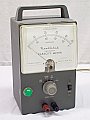
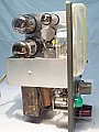
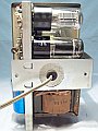
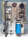
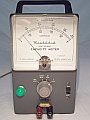
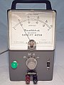
Circuit description.
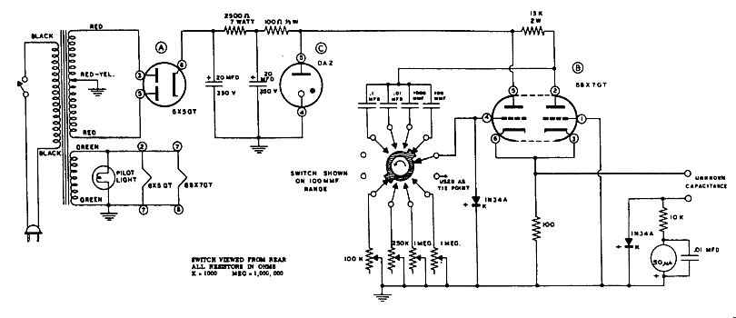
- The measuremet of capacity is accomplished by rectifying
a square sided pulse and reading the average value of the voltage on a
meter.
- A power transformer, 450 volt secondary center tapped,
in conjunction with a 6X5 rectifier tube and an OA2 voltage regulator tube,
supplies regulated voltage for the oscillator.
- The oscillator uses a 6BX7 tube in a cathode-coupled
multivibrator circuit, and applies a square sided pulse to the capacitor
being tested. The frequency applied is about 120 Kcs, 11 Kcs, 1050 cs,
100 cs, depending on scale. The AC current which flows as a result, is
proportional to frequency and capacitance. When the capacitance of the
capacitor being tested matches the reference capacitance of the multivibrator
the meter indication is maximal, for the rest is proportional, the meter
always indicates a value proportional to the current flow. A 100 ohm cathode
resistor provides the common impedance necessary to maintain oscillations,
and it is also the source impedance of the pulse used for measure the unknown
capacity connected in the binding posts of the panel.
Repairs: The filter capacitor 2 x 20 µF 350 volt was found
totally damaged, it was replaced by a 2 x 50 µF 350 volt electrolytic.
Two reference caps on the range switch (.1 and .01 µF) were found
leaky, same occurs with the .01 µF paper capacitor in parallel
with the meter, they were all replaced.
Using the Direct Reading Capacity Meter.
Simply clip the capacitor to be tested across the binding
posts and read the value on the meter scale. In case of doubt when testing
an unknown capacitor, start with the highest scale and work down until
a proper measurement is found. Leaky capacitors always show increased
readings, the same that occurs with the modern capacitor testers.
Very useful in measuring air variable capacitors. This instrument gives
excellent operation and surprising accuracy, the only drawback is that
it only can do measures up to 100 KpF !!!
|