

Some thoughts on the Heathkit HW-101 (part 2)
On this page:
- The series/parallel layout of tube filaments in Heathkit transceivers (balancing filament lines with #44 and #47 pilot lamps).
- The tubes in the HW-101: Originals vs possible replacements (replacements with similar aftermarket tubes).
- ← HP/PS-23 Power Supplies and Heathkit transceivers - CW operation & sidetone - Mods & Customization
(Number of wires actually needed in patch cords for Heathkit transceivers, sidetone options for the HW-101, service bulletins and customization).
#1 Filaments in series is never a good design because real filament amperages are not exact to specs.

This design is very common in Heathkit transceivers. Regarding pilot lamps, the HW-101 manual calls out #47 pilot lamps (.150 A, referenced in the replacement parts list as #44), but every HW-101 has #44 pilot lamps (.250 A). Service bulletin HW-101-20 refers to this. To make the total of 12.6 volts the HW-101 tubes are connected in series-parallel using two 6.3 lines in series as shown above. Some tube filaments can be connected to 12.6 volts: V16 (12AU7), V17-V19 (12AT7). The rest are 6.3 volts only: V1-V12-V5-V15 (6EA8), V2-V3-V4-V20 (6AU6), V6 (6CB6), V7 (6CL6), V8-V9 (6146), V10-V11 (6HS6), V13 (6BN8), and V14 (6GW8). Note above that V10-V11 are labeled 6AU6 because HW-100 has 6AU6 for V10-V11 instead 6HS6; this part of the schematic was never updated.
Filaments configuration: Tube designation and (filament Amp). 4 groups of 2 tubes in series at left, global group of tubes in series/parallel at right.
| A to Ground | V2 (.3) & V16 (2 x .15) | V3 (.3) & V4 (.3) | V17 (.15) | V19 (.15) | |||||||
| A to B | V8 (1.25) | V15 (.45) | V10 (.45) | V7 (.65) | V12 (.45) | V5 (.45) | #47 + # ? | ||||
| B to Ground | V9 (1.25) | V14 (.66) | V11 (.45) | V6 (.3) | V13 (.6) | V1 (.45) | V20 (.3) | ||||
The theory:
• Sum of the 4 'A to Ground' independent tube groups at upper left: 0.9 amps.
• Sum of the 6 'A to B' combined tubes (except pilot lamps) at middle right: 3.7 amps.
• Sum of the 7 'B to Ground' combined tubes at bottom right : 4.01 amps.
• Difference to match lines 'A to B', and 'B to Ground': .31 amps.
• And this is where the pilot lamps come into play. Pilot lamp #47 is .150 amp each, thus total is .3 amps to add to line 'A to B' = 4 amps.
• The total filament amperage draw 'A to B' would be 4 amps (4.01 amps for 'B to Ground') of the combined groups + 0.9 amps total of the independent group = 4.9 amps 'A to B' and 4.91 amps 'B to Ground'. That is, by design .01 amps unbalanced, which is negligible. In these conditions the voltage on each line should be the same (about 6.3 volts) , thus each 6146 would have same voltage and amperage across filaments.
The practice:
Table above shows pilot lamps loads the 'A to B' circuit, only. When balanced, if totally possible, each circuit 'A to B' and 'B to Ground' will have same voltage, and this means that both have the same amperage. The 'A to Ground' circuit does not count for this as it loads the entire filament line. Checking filament voltage in a HW-101 is very easy as the test points are the two terminals of the front pilot lamp and ground; terminal with white lead is line A, terminal with brown lead is line B (if they have been connected as indicated in the manual).
• To check 'A to Ground' (12.6 volts) = White and Ground.
• To check 'A to B' (6.3 volts) = White and Brown (the two terminals of the pilot lamps).
• To check 'B to Ground' (6.3 volts) = Brown and Ground.
If after 5 minutes of warm-up, the 'A to B' and 'B to Ground' voltages are fairly equal (difference is less than .1 volts), your HW-101 is fine regarding pilot lamps configuration and tube filaments consumption, it doesn't matter if there are #47 or #44 pilot lamps installed, you're done.
If not pull out the pilot lamps, power on, and measure voltages from 'A to Ground', 'A to B', and 'B to Ground'.
- As an example, the voltages without pilot lamps on this particular HW-101 are 12.6 - 6.9 - 5.7 (respectively, 230 VAC mains). 6.9 volts on 'A to B' indicates that we need to add more amperage load on this 'A to B' line to balance both lines, the two pilot lamps load this line only, but since the filaments are in series, it must be taken into account that when loading the 'A to B' line, the 'B to Ground' line will react by increasing voltage, which is what is intended.
- There are #44 (.250 A) and #47 (.150 A) pilot lamps available. This means there are 3 values to load the line 'A to B': At maximum with .500 A (two #44), minimum with .300 A (two #47), and in between with .400 A (#44 + #47). In theory, of course, since as with filaments, pilot lamps can also differ from standard specifications.
- The easiest empirical method is to install #47 + #47 and see the results. If there is still a difference to match, it means that now we have to replace one #47 by #44 and measure again, and if there is a little more left to match, maybe you have to replace the other #47 by #44. It's about getting closer to the closest value that balances the two lines. This particular HW-101 needs a #47 + #44 pilot lamp configuration. Now the voltages will be quite the same (differences of up to .1 volts can be considered normal for this type of networks).
- An additional option to balance lines is interchange 6146 since they are totally in parallel in the final stage (there shouldn't be capacitive or inductive effects). Like filaments in series, tubes in parallel is not a good design either as nothing guarantees that they will age 'in parallel', so there may be amperage differences in filaments.
- There is the option to charge 'B to Ground' with "something" of 6.3 volts to have more amperage available in order to charge 'A to B' (pilot lamps).
- There is the option to charge 'A to ground' with "something" for a total of 12.6 volts but with a single amperage or same amperage in series.
- — To know that only when replacing in any of the 4 groups of 2 tubes in series (above left) both tubes must have the same amperage.
- — When replacing tubes of the global group (above right), different tube amperages can be placed on one line, but will need to be compensated for with other tube filament amperages on the other line, or with different pilot lamps amperages (voltage has to always be 6.3 of course).
- — It is always advisable to retest filament voltage at the ends of the pilot lamps to see if the balance between filament lines is still OK.
- — Unbalanced lines may affect power tubes filament emission (which are included in the global series/parallel network).
#2 Printed circuits limit the ability to make replacements with reciprocating tubes and restrict mods.
Printed circuits restrict freedom on replacements/mods turning technological devices into throwaway appliances. There will be a problem if a tube mounted on a printed circuit cannot be replaced by another of the same type and same pin architecture. In this case the affected printed traces must to be interrupted and re-circuited with external wires, which can cause issues, for this reason when working on PCBs we need to know tube socket equivalences, not tube replacement chances, this can only be done on chassis mounting. Therewith, as shown in the previous paragraph, since filaments are in series in 4 independent groups, and series/parallel in 1 two-line global group, when replacing one tube with another that has different filament amperage implies to replace associated tube/s and recalculate the group. It is important that you replace/correct LOAD on both sides (A/B lines), and/or take existing values into account to avoid unbalancing filament voltage. The original HW-101 tube 'line-up' is:
| Tube | US type | EU eqv / *Ic-eqv | Works as... | When... | Operational section/s |
| V1 | 6EA8 | — /see repl-opts | Mic amp | Transmitting | Pentode & Triode |
| V2 | 6AU6 | EF94 | Buffer amp | Transmitting | |
| V3 | 6AU6 | EF94 | 1st IF amp | Transmitting & Receiving | |
| V4 | 6AU6 | EF94 | 2nd IF amp | Receiving | |
| V5 | 6EA8 | — /see repl-opts | 1st mixer | Transmitting | Pentode - Triode (this section is not used) |
| V6 | 6CB6 | — | 2nd mixer | Transmitting | |
| V7 | 6CL6 | — | Power driver | Transmitting | |
| V8 | 6146 | QE05/40 | Power amp | Transmitting | |
| V9 | 6146 | QE05/40 | Power amp | Transmitting | |
| V10 | 6HS6 | — /see repl-opts | RF amp | Receiving | |
| V11 | 6HS6 | — /see repl-opts | 1st mixer | Receiving | |
| V12 | 6EA8 | — /see repl-opts | Relay amp - 2nd mixer | Transmitting - Receiving | Triode - Pentode |
| V13 | 6BN8 | — | Detector - AVC rect | Receiving | Triode - Diode & Diode |
| V14 | 6GW8 | ECL86 | AF amp | Receiving | Triode & Pentode |
| V15 | 6EA8 | — / 6U8 ECF82 | Tone osc & amp | Transmitting | Pentode & Triode |
| V16 | 12AU7 | ECC82 | XFO & BFO | Transmitting & Receiving | Triode A (LSB/CW) & Triode B (USB/BFO) |
| V17 | 12AT7 | ECC81 | VOX amp - Calibrator | Transmitting - Receiving | Triode A - Triode B |
| V18 | 0A2 | — | Voltage regulator | Transmitting & Receiving | |
| V19 | 12AT7 | ECC81 | Heterodyne osc & buffer | Transmitting & Receiving | Triode A & Triode B |
| V20 | 6AU6 | EF94 | VFO amp/buffer | Transmitting & Receiving |
• Most of these tubes come from ordinary TV and radio circuitry; some of them are getting scarce.
• If originals are not available, most of these tubes are fully substitutable with similar ones, also coming from the same type of circuitry, and in circuit will do the job just as effectively. The problem that arises is pin matching, the alternative is to interrupt the traces to tube sockets and make jumper connections, but that is always best avoided. Another important point is the filament consumption of the new tube and its insertion in the correct place of the series/parallel system, that's why it is described above.
*Ic-eqv : In-circuit equivalent → to apply only to the particular circuit.
Original 6HS6 Miniature tube at left, and possible/known equivalences at middle / right. (Tube graphics: De Muiderkring Tube Handbook, 1966)
The 6AU6 to 6HS6(A) change was implemented in the HW-100 due complaints on sensitivity on 15 and 10 meters. The 6HS6 mod did not come from Heathkit engineers: A Ham who was employed at Heathkit, Jim Isham (W8TXX), did some tests with other tubes noting that a HW-100 with 6HS6 tubes worked better on sensitivity, then Heathkit checked it out and implemented 6HS6 in future production. That's why it's fun to see that currently there are some claims about go back to 6AU6 by the same reasons which it was originally included in HW-100. BTW, the receiving section of the HW-101 constitutes one of the best designs of a receiver integrated in a transceiver at that time, especially with the 6HS6 change to do the job of V10, which is the tube specifically involved in sensitivity. The performance of the HW-101's receiving section is similar to that of many of standalone receivers operating in T-R configuration. I suspect that 6HS6 gives higher gain not only because it has higher transconductance, but because its internal resistance better adapts to the real impedances of the existing coils (relatively low, VERY similar to tube-TV coils designed with impedance scaling techniques). When trying to do the same with higher impedance coils, what is gained with transconductance is lost with mismatch. The two 6HS6 can be replaced by two 6AU6, making this tubes a 'back to the future' experience because they were the original tubes in the main design of this transceiver (HW-100). 6AU6 has .3A filament, 6HS6 has .45A filament, each A / B line has one 6HS6 tube, when replacing one tube, the balance of both filament lines should be considered. It is possible to replace V10 only (which is on the 'A to B' line) if .150A of less is compensated (.450 6HS6 vs .300 6AU6) by replacing one pilot lamp or both with another/others of more amperage (#44). Now the two pilot lamps should draw .150A more than before to balance with the 'B to Ground' line. Returning 6AU6s to each line, both lines remain balanced, and total amperage relaxes .150A. Tryed with 2 new 6AU6 tubes, and I can confirm that the original change from 6AU6 to 6HS6 is correct, my 'Hot Water' warms the water more, it has better sensitivity on all bands. I have not reviewed in detail other considerations, but it is common that when the sensitivity increases other aspects, such as cross modulation, get worse, particularly in simplified receivers, like those of all the transceivers of that time. IMO to get the best of both worlds (sensitivity - cross modulation) is to combine 6HS6 (.450A) for V10 (RF Amplifier) and 6AU6 (.300A) for V11 (First Mixer), it works perfect, but filament balance needs to be readjusted by removing .150 amps from the 'A to B' line by pulling out a #47, or by sharing .250 only on two pilot lamps: .150 (#47) + .100 (#?). Remember that this amperage distribution is for my particular HW-101 (YMMV, read above). The solution in this case is to return to the #47 + #47 configuration = .300 amps, so only .050 amps will be misadjusted, which is acceptable. There are other options about replacing V10 and V11, questionable but possible. 6BA6 (EF93) is compatible with 6AU6, and can be temporarily installed replacing V10 or V11. The most important difference between those two is that 6BA6 is a tube designed specifically for AGC, in the rest it is like 6AU6. Combinations 6AU6 + 6BA6 and 6BA6 + 6AU6 can be made because those two types have the same filament amperage (.3), they all work OK, although the best would be 6AU6 as RF amplifier because it has a little more 'S' (transconductance). 6BA6 is less "hot" than 6AU6, it will work well on reception, but would not be suitable on emission. And for the same reasons 6HS6 can be replaced by 6HR6. It is not initially advisable to replace V2, V3 (6AU6) with other types since they are associated to the Xtal filters and both tubes are used on transmitting. |
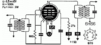
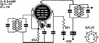
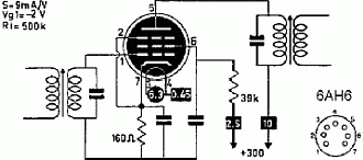
|
Heathkit replaced the original V10-V11 6AU6 tubes by 6HS6 in 'raw-ham style', HW-101 circuit values for V10 and V11 are the same as HW-100. 6HS6 is a tube for a lower voltage range, but this difference was neither compensated nor redesigned in the HW-101. A possible explanation for this is that the value of the cathode resistors are higher than the standards for those tubes, so they probably considered that the amperage that passed through them was under control and it was not necessary to do anything. But on the other hand, the abundance of tubes at that era caused a lot of "savagery" with them, it did not matter if they had to be changed often, and also the tubes held/hold "savagery" very well, nothing to do with transistors. Now this has changed, we have to treat tubes with greater care, many of them are already scarce, and some of those are priced high fidelity without having anything to do with music. Therefore, it is possible to reinstall 6AU6 tubes without worries because they would revert to the exact circuit that was originally designed for them, but at the cost of lowering sensitivity. By comparing the 6HS6 with the 6AU6 circuit schemes of above, we can see that 6AU6 is a tube to work with a 250 volt B+ line, and 6HS6 a tube to work with a 150 volt B+ line. These two tubes are similar, the difference is that 6HS6 is designed to operate with lower load impedances than 6AU6. When using 6HS6 in a circuit designed for 6AU6, 6HS6 will work at excessive voltage, even though precautions have been taken with cathode resistors values. That is, both plate and grid screen have enough voltage that its performance can no longer go higher, it is simply a way to burn up a tube, this is the "savagery" that I'm referring above. Therefore, it's better to try applying more "civilized" voltages: 6HS6 V11, first receiver mixer: No need to tweak voltages here as V11 works with a 100 Kohm screen grid resistor, thus reducing voltage to safe levels. Here, the circuit design is reasonably suitable for direct switching from 6AU6 to 6HS6. 6HS6 V10, RF amplifier: R409 is the screen grid resistor, if for a 6AU6 at B+ 250 volts, 10 Kohm is an awkward value, for a 6HS6 it is a killer value. The problem on replacing this resistor is that the solder points are located at the bottom of a 'grand canyon', and just below the edge of the driver grid switch-board. This means that the usual test and replacement process to find an adequate value for that resistor is high risk, and inserting a test variable resistor to find the exact value is cumbersome, so it has been chosen to move the R409 connections at the top by installing two lugs in order to comfortably find the correct value, and this also easily allows any future change. This will not cause RF problems, since this resistor is (it must be) totally RF decoupled. 56 Kohm is the highest value found that does not reduce the performance of the 6HS6, and curiously or not, it is twice the standard value at B+ 150 volts (see graphic above); this shows the 6AU6 screen grid is fully saturated at 230 volts even with a 10 Kohm resistor. The new screen grid resistor reduces 230 volts to 170 volts, which is certainly a more "civilized" value for the screen grid of a 6HS6, "a 150 volt tube". It is not possible to adapt plate voltage, since it would be necessary to install a decoupling network next to the corresponding reducing resistor. Despite continuing to operate within maximum rates, this will give to 6HS6 longer life for same performance. 6AU6 V4, 2nd IF amplifier: The same previous case but on smaller scale. R113 is the screen grid resistor, 1 Kohm is also an awkward value on receiving, it is a transmitting circuit value, not a receiving circuit value. Replacing R113 for a variable resistor of up to 50 Kohm shows that the value does not affect gain, so the applied voltage is more than enough (as was the case with V10). The standard value of 22 Kohm is installed (see graphic above), V4 plate voltage is 250 volts, with 22 Kohm at screen grid voltage drops to 210 volts, which is a very correct value (high-side) for a tube designed to work with a 250 volt B+ in receiving configuration. V4 also works with increased value cathode resistor, cathode voltage is 1.8 volts, a bit high but a safe polarization value. These tubes are used for receiving only, so there is no need to 'burn volts' to 'fire watts', it is better to apply healthier screen grid voltages in order to obtain longer tube life. |
Original 6EA8 Noval tube at left, and possible/known equivalences at middle / right. (Tube graphics: De Muiderkring Tube Handbook, 1966)
|
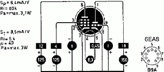
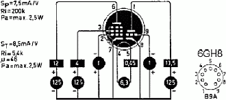
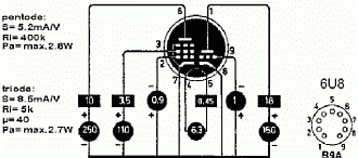
Don't know why, but 6GH8 (or 6GH8A) is often assumed to be a direct replacement for 6EA8, this is not correct, they are similar but not equal. 6EA8 has direct replacement (same specs), but with different pinout, in the 6EU8 tube (mouseOver 6EA8 graphic).
6EA8 is a two section tube that has a pentode section with a medium Ri which is better for a transmitting layout, so more attention should be paid to this replacement. There are two options at right: filament voltage and amperage are identical, the biggest differences are in the pentode section that both shows a reception-friendly layout (Ri). 6GH8 triode section is quite similar to that of the 6EA8, the biggest differences are in the pentode section (as in 6U8), but 6U8 triode section is identical to 6EA8, so it can be an alternative (Collins Radio used 6U8 on their transmitters).
First off, the tube replacement search process consists in analyzing parameters and possible behavior of the new tube in the involved circuit, but when using printed circuits the pin configuration must be taken into account seriously, this adds more difficulty to the selection process. When making these types of modifications, attention should be paid to design performance ratios and maximum construction ratios, actual applied voltages should never exceed the latter. When working above operating voltages, it is strongly recommended to increase cathode resistor values to provide safe bias for a "good tube health", and to work at a more correct point on the expanded load line. Many circuits already work preventively with increased cathode resistors values.
The tube that needs the least analysis to replace is V15 (tone oscillator). It is a simple AF oscillator (pentode) with a bias switched amplifier circuit at its output (triode), for such a simple job any tube of above to the right will work fine, others may need a higher value of cathode resistors or a decrease in B+ on the plates, many not even that. 6U8 (ECF82) is a great candidate because triode sections of 6EA8 and 6U8 are practically identical (I have made this change on my HW-101). BTW, a 6U8 has close replacement in 6AX8; and the triode section of the 6LM8 is equal to the triode section of the 6GH8; also, tweaking resistor values a 6BL8 could also serve to replace V15. The second simplest is V1 (speech amplifier), priority here is good microphone amplification and very good adaptation to the balanced modulator, therefore, it is important to have a triode section similar to the 6EA8 triode section, and a pentode section with performance. Referring to V12 (second receiver mixer and relay amplifier), the triode section must match the relay load. And finally V5 (first transmitter mixer), the pentode section must adapt perfectly to the circuit, the triode section does not matter as it is not used here, so this tube could be replaced by a Noval type pentode that have a medium Ri for example, but in this case the pin coincidence would be impossible, and here we have a good example that printed circuit boards restrict the ability of making mods.
To be continued... on the fly, with the rest of the HW-101's TV and radio tubes.
| Component ID | Type | Works as... | When... | Comments |
| Q941 | MPF-105 | VFO | T & R | FET transistor. |
| Q942 | 2N3393 | Zener limiter | T & R | NPN transistor, colector unused. |
| CR941 | 1N191 (Ge) | DC switch | T & R | Diode, adds/removes SHIFT ADJ trimmer. |
| D202 | Zener 15V | Voltage limiter | T | Diode, cuts-off V12B VOX anti-trip. |
| D201 | 1N2071 (Si) | VOX rectifier | T | Diode, VOX Amp V17A audio signal rectifier. |
| D1, D2 | 1N2071 (Si) | Anti-trip rectifiers |
R | Diodes, V14B audio signal full-wave rectifier. |
| CR1, CR2, CR3, CR4 | 1N191 (Ge) | Balanced mod. | T | Diodes, ring connection, RF & Audio signals mixer. |
| CR201 | 1N191 (Ge) | Harmonic gen. | R | Diode, crystal calibrator output to receiver input. |
| CR901 | 1N191 (Ge) | RF sampler | T | Diode, REL POWER output rectifier. |
| D301 | 1N2071 (Si) | DC switch | T & R | Diode, removes/adds -DC to V5A, V6, and V7 grids. |
| D901 | 1N4149 (Si) | DC switch | T & R | Diode, blocks +DC return for fast receive operation. |
| D902, D903 | 1N2071 (Si) | ALC rectifiers | T | Diodes, half-wave voltage doubler. |
| D904 | 1N2071 (Si) | DC switch | R | Diode, gives cutoff BIAS to V5A, V6, V7 grids (CW). |
| D905 | 1N2071 (Si) | DC gate | R | Diode, prevents RF gain interact with AGC source. |
| D101 | 1N2071 (Si) | DC gate | R | Diode, prevents AGC source interact with RF gain. |
| D907 | 1N2071 (Si) | DC switch | T & R | Diode, removes/adds C955 to ground. |
In order to work on a HW-101 it is essential to have the complete schematic on a large sheet, it is the only way to see how the stages interact. It is also highly recommended to have the manual.

|
Usual equipment that may be required to check and adjust these rigs: A tube tester to check current condition of the tubes, especially those used on transmitting; a VTVM or DVM for testing voltages and resistors, a capacitor tester to check the electrolytics of the HP-23 power supply in order to evaluate a possible reform procedure (if these capacitors are of good manufacturing quality, have not been "punished" by start-ups, and have not dried, it is perfectly possible to reform them); a dummy load; a receiver or a digital frequency counter are also useful for checking output frequencies via proximity coupling; you do not need modern gear at all, the frequency counter is the exception.
