

Some thoughts on the Heathkit HW-101 (part 1)
On this page:
- HP/PS-23 Power Supplies, patch cords for HW & SB transceivers (only 8/7 wires are needed, 11-pin sockets are unnecessary).
- Sidetone on CW operation (if you like CW, you will probably need adjustable sidetone).
- Mods & Customization (you may need to apply some Heathkit mod and maybe do some customization to personal taste).
- → Tube arrangement in the HW-101: The series/parallel layout of tube filaments in Heathkit transceivers. Originals vs possible replacements.
(balancing series/parallel filament lines with #44 and #47 pilot lamps; replacing originals with similar aftermarket tubes).
#1 - The Heathkit-23 power supplies, voltage outputs & number of wires needed in PS patch cords.
The 1960's Collins S-Line produced a significant imitative impact on other manufacturers, it seems that they were trying not only to compete in electronics but also aesthetics. Heathkit was one of the imitators, and when trying some compatibility, it appears Heathkit designed the HP-23 power supply with the idea of making it compatible with the Collins 516-F2 power supply that has an 11-pin output. Heathkit-23 power supplies not only provide same voltages as the 516-F2, they have one more B+ LV output option, and being solid state also provide excellent regulation. The superior inductance filtering of the Collins PS is compensated in the Heathkit ones by the use of higher capacity filter capacitors, so it is not unreasonable to argue that they were most likely designed to compete at much lower cost.

Models: All of these PS have 800 HV and 11-pin output plugs (output voltages under average load at nominal VAC input).
- HP-23: 120 VAC input, has 12.6 and 6.3 VAC filament outs, fixed AND adjustable BIAS adjust, fused plug, PILOT lamp and ON/OFF switch on front, alternate internal connections for 250VDC / 300VDC outputs. Export version HP-23E = HP-23 with dual winding input for 240 VAC. General purpose power supply (1963), 10 output pins connected.
- The secondary HV AC winding of the subsequent HP-23 models (see below) have slightly higher HV secondary output (282 VAC) than in the first model, which is 268 VAC. Therefore, the previous model will provide an average B+ high voltage of less than 800 VDC (note the above measurements are at no load). 6146 is a 750 VDC max B+ tube, but power supplies must provide the effective voltage under dynamic conditions, and this is why there is always an upward voltage difference in the static measurement. When a power supply is designed to supply a lot of power, the voltage difference between static and dynamic measurement is usually small. Perhaps Heathkit realized that the average dynamic voltage dropped a little to supply the design power and increased the HVAC output in subsequent models.
- HP-23A: 120/240 VAC input, has 12.6 and 6.3 VAC filament outs, fixed AND adjustable BIAS, circuit breaker, ON/OFF switch COMBINED with alternate 250VDC / 300VDC LV outputs. General purpose power supply (1968), 10 output pins connected.
- HP-23B: 120/240 VAC input, 12.6 VAC filament out ONLY, NO BIAS adjust, circuit breaker, ON/OFF switch COMBINED with alternate 250VDC / 300VDC LV outputs. Power supply devoted to Heathkit transceivers (1973), 8 output pins connected.
- HP-23C: 120/240 VAC input, 12.6 VAC filament out ONLY, NO BIAS adjust, circuit breaker, ELIGIBLE internal connection 250VDC or 300VDC for LV output. Power supply devoted to latest Heathkit tube transceivers, 8 output pins connected.
- PS-23 = HP-23C: It seems that at some point the Hewlett Packard Company did not let the Heath Company use 'HP' as a designation for their products, so HP-23C became PS-23.
There are not any Heathkit transceiver that needs more than 8-pin connection, in fact 7 is strictly enough because a wire from the 12.6 VAC filament output (e.g. FIL COM) can be grounded at the power supply and disconnected from ground at the transceiver, leaving free in this manner one of the 8 wires of the patch cord for another use; e.g. an extra pin on the HW-101 socket may be required for connection to the relay for linear amplifier operation (although there is a much better solution for this using the SPARE RCA plug as Heathkit suggests in the manual). Second-hand HP-23 and HW-101 units can be found with some ease, what is usually missing is the PS patch cord. The 11-pin connectors were not as common as the 8-pin ones, as Collins uses 11 pins, the result is that when something scarce is combined with a luxury concept, the price is notoriously expensive. It is also not fine design to use connectors with a lot of spare pins, so the octal connector is the correct design for interconnecting Heathkit transceivers. A colored eight-wire patch cord is not difficult to make or purchase; if 8 pin amphenol plugs aren't accessible, an 8-pin tube socket is easy to have, and a male 8-pin tube plug can be obtained from a dead pentode. And about thickness; for a correct design the one that supports 800 volts should have a little more thickness of insulating plastic, not wire thickness, the thicker wire should be for the filament wires, or one filament wire and the common ground wire when the ground is built into the power supply, the remaining 5 wires can be standard.
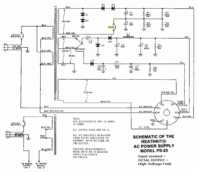 |
A slightly modified PS-23 circuit:
|
| Circuit of above applied on a HP-23B chassis. | |
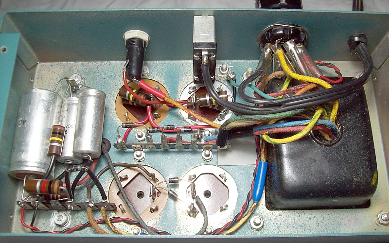 Practical implementation of the schematic above: some components relocated, fuse, now the output is by octal socket. |
|
| A 60 cm (23.6 inch) 8-pin power supply patch cord for the HW-101 transceiver. | |
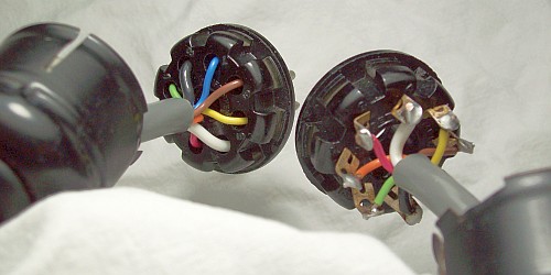 Longer lengths may require a female plug with cable clamp attached to prevent wire twisting next to the solder causing it to break. |
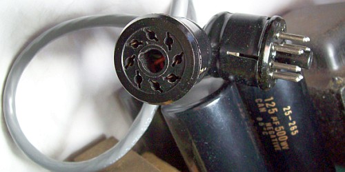 PS to HW-101 patch cord finished. See 'preventionally reformed' original Nichicon 125µF / 500V filter electrolytic capacitors at bottom right. |
HW-101 rear panel. |
|
 |
|
| Mods: 8 Ohm Phone output, Relay RCA socket for linear, Power 8-pin, and Antenna SO-239 connector. | |
#2 - CW operation. Sidetone options for the Heathkit HW-101.
General CW operation procedure:
- The initial set up: BAND and dial to desired frequency, METER to PLATE, MIC/CW full counterclockwise, antenna or RF load to the ANTENNA connector, MODE to TUNE, checking 50 mA at the V mark (BIAS adj), METER to REL PWR, LOAD lever at 4 o'clock position, FINAL matching with BAND position.
- The LOW level adjust: MIC/CW clockwise until a small up-scale meter indication is achieved, then adjust alternately PRESELECTOR, FINAL, and LOAD lever for a maximum indication on the meter (PRESELECTOR needs accurate adjust).
- The HIGH level adjust: MIC/CW clockwise until the meter reading no longer increases, then peak alternately FINAL and LOAD levers for a maximum indication on the meter, METER to PLATE to read about 40 that indicates a plate current of 250 mA, MIC/CW to full counterclowise.
- The CW operating adjust: FUNCTION to PTT or VOX, MODE to CW, key to CW KEY and VOX DELAY adjusted to keying speed, MIC/CW must be set to the minimum position achieving maximum output.
Pics below: SB-101/2 sidetone adjustment and schematic, the inner potentiometer is easily accessible through a flip cover. HW-101 has fixed covers. Next 2: HW-101's original circuit. On the right: sidetone mod in this particular HW-101, but there are other options.
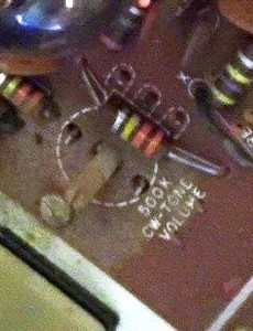 SB-101 sidetone, internal volume adjustment. |
 SB-101 sidetone, volume adjustment circuit. |
 HW-101, no sidetone adjust on circuit. |
 HW-101 schematic, pre-adjusted sidetone. |
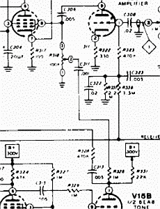 A sidetone mod making R318 adjustable (see text). |
The SB-101 sidetone circuit can be replicated on a HW-101 since the tracing layout still remains on the HW-101 PCB, albeit without components. The problem is that the HW-101 does not have a top cover to be opened on the fly, so if the potentiometer is inside, it can only be set each time the lid is removed, or by making a hole in the lid. To be easily accessible the sidetone potentiometer must be installed on one side of the chassis, in a similar way to the rest of the adjustment potentiometers; this implies some wiring, that may cause coupling problems. The most "mfg-style" option would be to install the SB-101 sidetone components on the HW-101 printed circuit except the adjustment potentiometer, that should be installed on one side looking for an available space.
There are some Ham variations of the SB-101/2 circuit. A previous owner included external sidetone adjust on this particular HW-101 in a very efficient and simple way, he simply turned the R318 fixed resistor into variable and voila, the only drawback of this design is that the printed circuit trace that goes from C311 to pin 8 of the 6GW8 tube has to be 'mechanically' interrupted. A pass-thru terminal is added to give a suitable solder point to connect the sidetone potentiometer. This design has the advantage that the wires to the sidetone potentiometer (R318, 100 Kohm in this case, 500 Kohm if you use the SB-101/2 circuit) are as short as possible (otherwise they should be shielded). There is also the option of placing the potentiometer on the rear using shielded wiring.
Heathkit 'fixed' the complaints about the side tone volume in bulletin HW-101-16 stating that R326 (1 Mohm) should be increased to 3.3 Mohm. Later, on HW-101-70, implemented the SB-101 circuit (described above) as standard modification.
#3 - Upkeep, Heathkit mods/bulletins & customization.
Neutralizing 6146s, alternate method. Link opens small window.
Service Bulletins for the HW-101 transceiver. Beginning 1971 (HW-101-1), ending 1989 (HW-101-85), and more.
Examples:
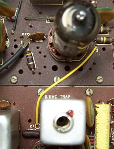 A) HW-101-14, improve ALC adjustment. |
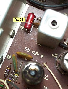 B) S-Meter drifts, a tube/resistor issue. |
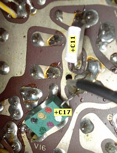 C) Adding capacity: BFO and modulator. |
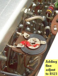 D) Audio: IF output adj to balance signal with BFO. |
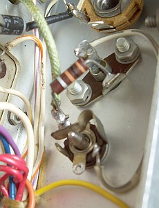 E) Additional phones jack with speaker muting (see sch below). |
- ) HW-101-14 of 1977 (improve ALC adjustment) is probably the most popular Heathkit mod. This change is already incorporated in later model HW-101s, so this mod divides Hot Waters in two: before / after 1977.
- ) S-Meter drifts (S-Meter instability) is also very popular: HW-101-10, HW-101-20, HW-101-34, HW-101-82, and Ham contributions. The HW-101's RF gain and S-Meter circuit is of the Collins S-Line type (simple) due it uses the AGC line to control grids, not a specific RF gain line independent of control grids. Thus, when we reduce signal gain (which is the correct procedure to avoid demodulator saturation), the S-meter tells us that we are receiving a lot of signal, which is absurd. HW-101's AGC is good enough that to avoid the RF GAIN control going back many times, usually it always stay at maximum. IMO the best S-Meter circuit is the used in Hammarlund HQ-170 and HQ-180 receivers, that separates AGC line from the RF GAIN control line.
V3 is related to the variable branch of the S-Meter circuit, therefore it will reflect variations in V3 control grid caused by the signal, but also the internal variations of the tube during operation due to aging. This becomes apparent when the HW-101 is cold, the S-Meter will mark above zero, and when it is hot, somewhat below, so best to adjust it after some time of operation(D). A "floating zero" behavior of the meter needle (not to be confused when the needle hooks a bit on the lower end of the scale and a light tap solves it) generally indicates a problem in V3, but there may also be dynamic value changes in resistors due to heating. Usually a new tube is the solution to this behavior because during heating time a new tube has much less internal variation than an old tube. The solution applied here was to replace the 6AU6 V3 tube and the R106 resistor. Now, right when the HW-101 is turned on, with RF GAIN fully clockwise, the meter goes straight to 60, backs off a bit below zero during warm-up, and when reception starts, it goes back to exact zero, and it never goes down from there when it works as S-Meter.
On HW-101-33 Heathkit advises a simple modification to try to correct the "floating zero" behavior consisting on installing a 2 Kohm resistor (or 10 Kohm adjustable resistor) between terminal 1 of relay 1 and the center terminal of the S-Meter zero adjust "for exact zeroing in both transmission and reception", this results in swing up of the meter needle on ALC/receive. There is also an internet mod that consists on adding a 10 Mohm resistor between lug #3 of zero adjust to pin 2 of T102, which is the AGC input to to V4. This causes that a small part of the negative AGC voltage to be injected into the fixed branch of the meter (R106 + R107 + terminal # 3 of the ZERO ADJ meter) making the voltage here less positive, the meter needle then moves up creating the need for a new zero setting. BUT, and here the drawback, as now the AGC voltage circulates through the two branches of the meter, it shortens scale reading range and also causes some AGC leak.
About this issue, and reading service bulletins, there is an incomprehensible unrelated reference to the R106 resistor, the HW-101-10 bulletin relates a mod for R107, which IMO is somewhat illogical. R106 is 22 Kohms 1 watt and supports the fed to the screen grid and, at a comparatively low drain, the fed to one arm of the S-Meter through R107 (100 Kohms) and the METER ZERO potentiometer. In my experience, the resistor that suffer is R106, not R107, for that reason R106 must be 2 watts. Some sources report that the value of R106 must go up to 33 Kohms, but it should not be forgotten that this stage also acts in transmit mode, and screen grid voltage has great influence on amplification. In my case nothing happens to R107, it is happy with 1/2 watt, it is R106 that suffers and varies its resistance as it heats up, acumulating overheats during time its value changes completely as shown in the pop-up pic.
- ) Adding capacity to improve signal level and frequency response.
C17 is the BFO coupling capacitor to the product detector, its value is 12 pF, but the previous owner increased coupling by adding 15 pF in parallel, thus 27 pF, that is a very correct value for BFO/PD coupling. Increase BFO/PD coupling serves to improve SSB demodulation with strong signals.
C11 and VOX issues. A 1 KpF capacitor couples MIC LEVEL to the balanced modulator and at the same time filters response. Its value was also modified by the previous owner by adding a .1 µF capacitor in parallel to give more "body" to the modulation. I consider this coupling capacity very excessive for an SSB modulator, but other than that, the main problem is that a high capacity value here facilitates circulation of a low frequency pulse generated by the associated relay when it disconnects via R301, R390, R12, C11 and VOX SENS. This 'speech' activates the VOX, and the relay starts to 'chatter' creating a loop that depends on the position of VOX SENS, that becomes critical. Returning C11 to its original value (1 Kpf), the circuit works fine, and VOX SENS does not have any critical position, it only controls the audio level to activate VOX. A value of 1 Kpf here seems too low to me, but increasing this value the circuit increases sensitivity to the relay pulse. To fix this, I follow the HW-101-57 instructions in order to eliminate the AC pulse, a 1 µF 100 V capacitor is installed across R308 to reduce pulse rise time (shunting AC pulse to ground), this allows C11 to be increased to 10 KpF without issue. Now the actual global 'speech filter value' (C9 + C11) is 5000 pF versus original value of 910 pF. This is the classic example where modifying something "for the better" without paying much attention to related circuits will harm the related circuits, perhaps the previous owner never used VOX.
- ) Audio! The most common concern in modern Ham radio. On receiving SSB, audio quality depends on tone (response) and DEmodulation quality. C306 is related to audio level and response to the speaker, R123 is related to signal injection level to demodulator.
AF response: C306 standard value is 5 KpF. Previous owner adds 10 Kpf in parallel, so total coupling is 15 Kpf, very enough, no more is needed.
IF level: DEmodulation quality depends on the correct combination of the local carrier (BFO) with the received signal, the insertion of the local carrier must be greater the simpler the demodulator. HW-101 has a Collins S-Line type demodulator (a simple triode), therefore it is a simplified demodulator that needs good carrier injection level. In a transceiver there are circuits that work both in transmission and reception, it is not advisable to act on them thinking only of one subject, the easiest procedure is to act in the place where only the desired subject operates. R123 is 470 ohms, this value may be adjusted applying a predetermined incoming signal level to the product detector in order to obtain good demodulation and signal-to-noise ratio (a cheap approximation to the principle used in the R-390A). I think it is better do not remove the 470 ohm resistor, so there will always be a fixed value if the contact of the variable resistor fails. A safe and precise method to adjust R123 is to leave it in the circuit as fixed maximum value, and then adding an adjustable resistor of higher value in parallel. Using a 5 Kohm resistor the variation obtained is excellent (up to 430 ohms), but the adjustable resistor needs to be logarithmic since at low values it does not have enough precision; therefore, a recycled 1 Kohm variable resistor has been used (see pic above), combined with 470 ohms it doesn't adjust as high (up to 322 ohms), but 1 Kohm has better adjustment in the low ohmic range.
- ) Additional Lo-Z phone out: PHONES output is designed for Hi-Z headphones. If Lo-Z phones are used, the outboard speaker will not mute completely with phones connected. Consumer-type phones are usually 8 Ohms, so they can be connected to the speaker 8-ohm line by inserting a dedicated jack. A switched 3.5 mm jack is installed on the rear, inserted in series into the audio line before the RCA socket that gives audio output to the external speaker. When plugged in, it will break the audio line to the RCA socket, when unplugged the audio will flow to the external speaker. With this simple modification a HW-101 is ready for Hi-Z and Lo-Z headphones.

The peculiar use of the RCA AF connector as RF power connector.
An RCA audio connector is not a suitable component to handle 70.7 volts RMS RF (100 watts) and a poorly bendable 50-ohm coaxial antenna cable which will persistently try to unplug it, so it is recommended to replace the RCA connector with an SO-239. Heathkit just copied it from Collins, but what would have been the comments if Heathkit had introduced RCA plugs as antenna connectors and Collins always used SO-239 ...? A fun QRZ.com thread here (copy n' paste URL:" https://forums.qrz.com/index.php?threads/why-did-collins-use-rca-phono-jacks-for-their-antenna-connectors.693372/ ". BTW, QRZ.com has restricted the open reading of their forums, now you have to register).
(A) HW-101's Dial Mechanism and Dial Calibration.
- Dual Jackson Brothers dial mechanism:
- - HW-101 has two Jackson Brothers ball drives, one is mounted on the front of the VFO while the other is mounted on the round mounting plate on the front panel escutcheon.
- - In the middle of this "sandwitch" there is the dial plate that "floats" between the large square dial mounting plate and the Jackson ball drive on the front of the VFO chassis.
- - The floating effect is achieved by a large plastic washer that acts as a clutch, i.e. the dial is never solidly attached to the rotor main bar, it is tightened by pressure. Mechanical excursion of the VFO and dial marking always remain separate, they are only connected by friction.
NOTE: Failures in this pressure lock may cause inaccuracies that can be misattributed to the Jackson ball drives. - - The zero button causes the dial to stop by pressure between its pivot and a fixed post on the front of the VFO chassis.
- To calibrate the dial:
- - Set it to any multiple of 100 Kcs mark (dial marks must be within the mechanical excursion ends). Move swich to the CAL position.
- - Press the ZERO SET button, and keeping the pressure on, turn the VFO knob to zero beat, the dial should not move. Release the zero button.
- - This would have to be done in EACH band to have calibration, since calibrating in one band does not ensure calibration in another band.
Unlike previous models, the HW-101's dial is not operated by a sliding ball reduction mechanism inside a shaft. Using Jackson drives, the ball mechanism only disengage when the excursion end is reached, never by calibration adjustments, this ensures long life to the ball bearings. A Jackson Brothers dial drive has 6:1 turn reduction for 360º. The VFO capacitor rotates only 180º, so the effective operation of the Jackson drive is 3:1. But since the HW-101 has two Jackson ball drivers rotating in tandem, they provide a total tuning ratio of 6:1 for 180º (demultiplying the one associated to the knob with the other associated to the VFO capacitor). The tuning knob makes 36 turns to cover all the markings on the dial, this excursion represents a 180º movement of the VFO capacitor.
(B) HW-101's Internet information examples (copy URL and paste it in a new window).- A thread with manuals and an excellent scan of the complete schematic in high resolution and single sheet.
- - HW-101 problem(s), URL:" https://groups.io/g/Heathkit-Radios/topic/hw_101_problem_s/75739889?p= "
- eHam.net's famous reviews.
- - Heathkit HW-101, URL:" https://www.eham.net/reviews/view-product?id=241 "
- QRZ.com threads with interesting info (no open read, registration needed).
- - HW-101 problems, URL:" https://forums.qrz.com/index.php?threads/hw-101-problems.277803/ "
- - Heathkit HW 101 Will Not Receive, URL:" https://forums.qrz.com/index.php?threads/heathkit-hw-101-will-not-receive.383189/ "
- Could not miss this thread which reports the same issue that was fixed by the previous owner on my HW-101.
- - HW-101 cooking R304, URL:" https://forums.qrz.com/index.php?threads/hw-101-cooking-r304.544999/ "
- An EXCELLENT JOB on the HW-101 ... URL:" https://www.frostburg.edu/personal/latta/ee/hw101/hw101.html "
- ... and a very good example of an 'American-style' restoration (which makes the device look brand new, as if it were manufactured yesterday). The drawback (IMHO) of this style is that it completely erases the device's history. I prefer the 'European-style' which is based more on "archaeological principles"; that is, restoring the device in a way that allows it to reveal the passage of time and the people who used it.
(D) An aged tube can take up 20 minutes to find its optimal filament (cathode) emission point, when a new one finds it in few minutes. An aged tube will continue to do its job, although with lower efficiency. Tube fatigue has more effect at high frequencies than at low frequencies, if fatigued tubes are used at low frequencies it may not be noticeable. There are also other reasons such as gas, but the difference is gas destroys tube operation, an aged tube works correctly, but at a lower speed. On receivers it is not necessary to obsess over the tubes, a demonstration of this, V3 (6AU6, IF amplifier), which is the tube that gave S-Meter instability at zero, now replaces V11 (6HS6, mixer), the difference in sensitivity is negligible. A tube can give problems to perform on some function, but in another it can work well as long as its gain be good, only local oscillators require special attention, also front-end RF amplifiers.

;)
;)