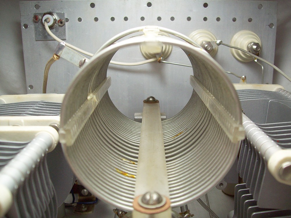
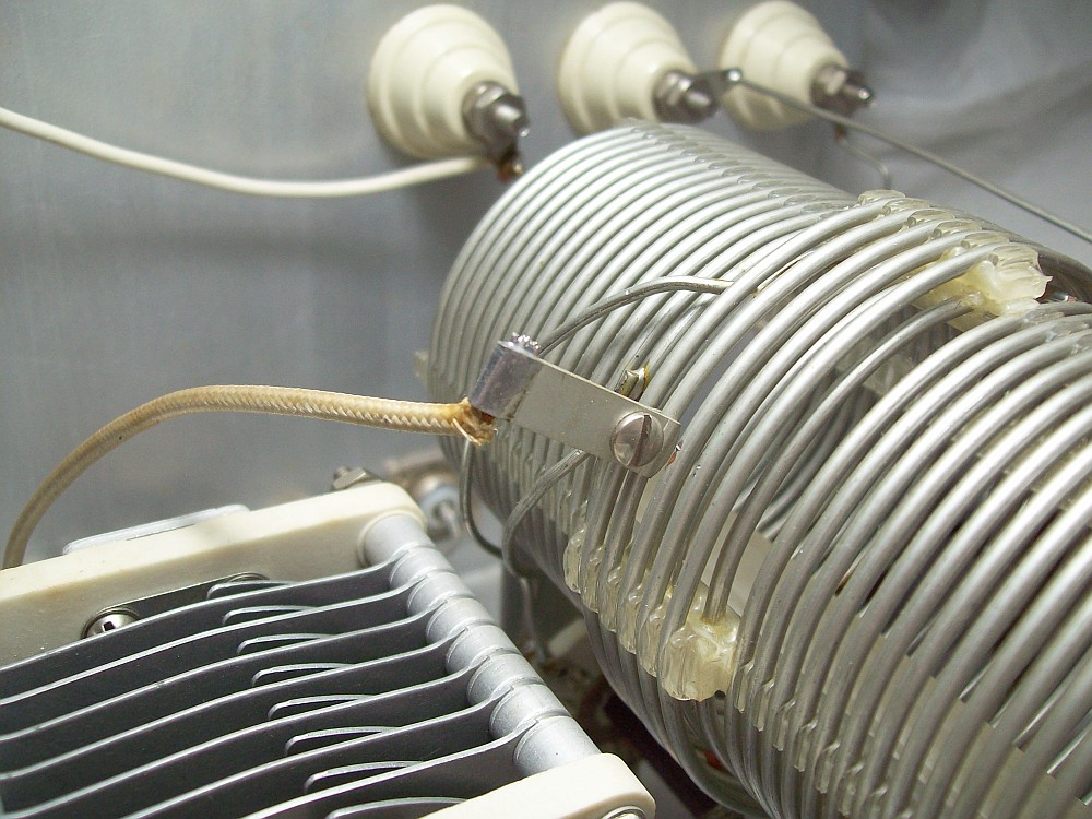
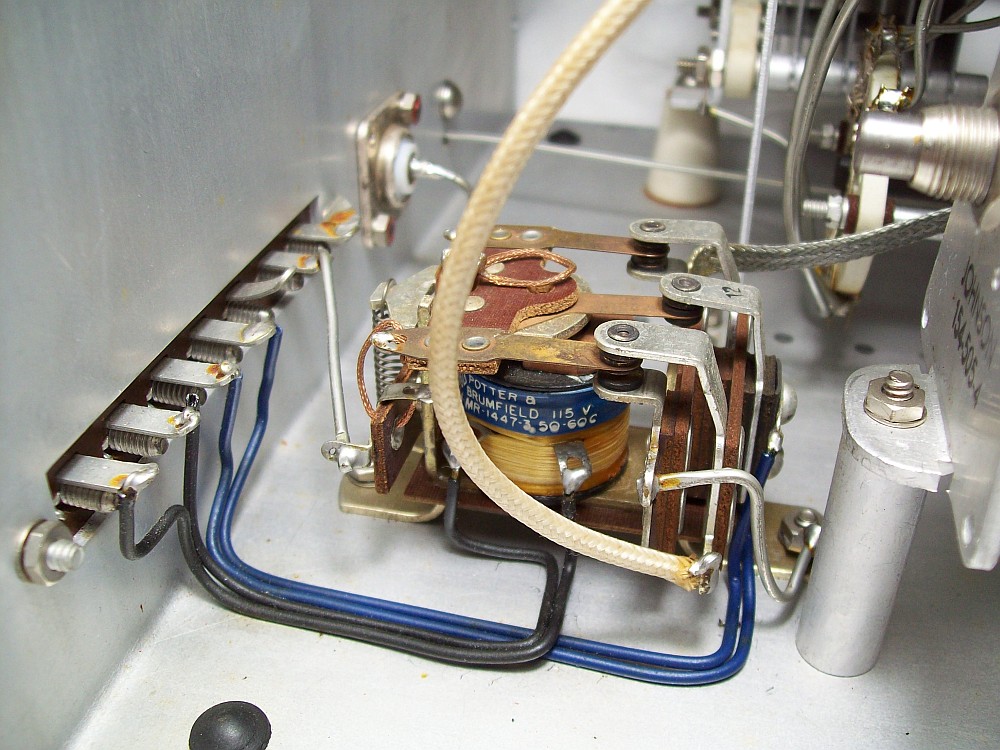
| Design & Specification |
| Frequency coverage, bands: |
* 3.5 Mcs (80 meters).
* 7 Mcs (40 meters).
* 14 Mcs (20 meters).
* 21 Mcs (15 meters).
* 28 Mcs (10 meters). |
| Modes: |
AM/CW by design (continous carrier or pulsed carrier). Therefore, on SSB there will be an additional amount of usable power available. |
| Models: |
• 250-23 for use with transmitters of 275 watts in AM/CW operation.
250-23-3 same as above, but including a Monimatch-type(2) SWR control at the input. Dimensions WDH: about 10 x 10 x 7 inches; 25 x 25 x 17.5 cms.
• 250-30 for use with transmitters of 1 Kilowatt in AM/CW operation.
250-30-3 same as above, but including a Monimatch-type(2) SWR control at the input. Dimensions WDH: about 17 x 12 x 10 inches; 44 x 31 x 26 cms. |
| Impedance matching range by model: |
→ 250-23 models (275): will try to match 50 ohm coax to
balanced-line loads ranging from 25 to 1500 ohm, and to unbalanced loads
of 25 to 3000 ohm.
→ 250-30-3 models (Kilowatt): will try to match 50 ohm coax to
balanced-line loads ranging from 50 to 1200 ohm, and to unbalanced loads
of 50 to 2000 ohm. |
Designed to be connected to:
Final tube amplifiers having...
• Link-type antenna outputs →
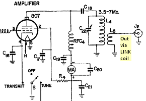
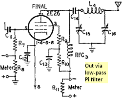
• Pi-type antenna outputs.... → → |
|
275 model (shown in the gallery above), schematic.
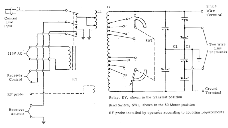 L1: 5 turns #10, 2.6 mm 1.8 spaced, same direction as L2, adjacent and centered. Taps from ground: 2 (50 Ω), 4 (300 Ω adjustable). L1: 5 turns #10, 2.6 mm 1.8 spaced, same direction as L2, adjacent and centered. Taps from ground: 2 (50 Ω), 4 (300 Ω adjustable).
L2: A = (14 turns #12, 2.1 mm 1 mm spaced) + B = (4 turns #12
double spaced, including both ends) + A (14 turns). Total 32.
L1 & L2 made of solid silver plated copper (CuAg) by B&W Airdux (or so it seems).
C1: 2 x 10-100 pF, 3 KVp variable standard capacitor Johnson 154-505-4 100ED30.
C2: 2 x 10-100 pF, 3 KVp variable differential capacitor Johnson 169-25 100EDA30.
LINE connections:
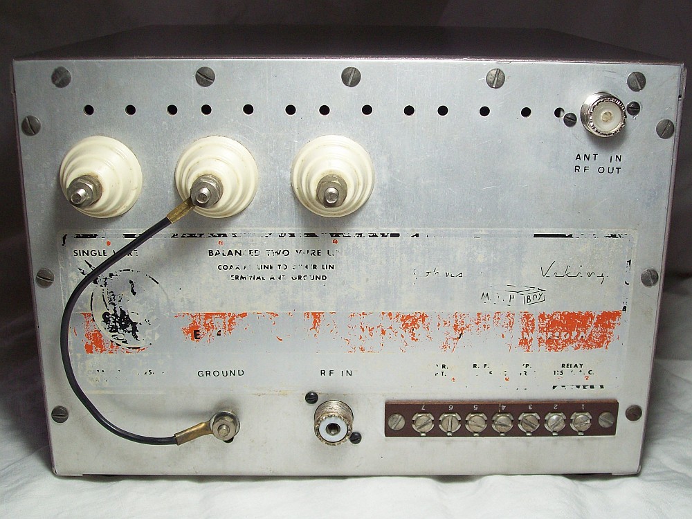
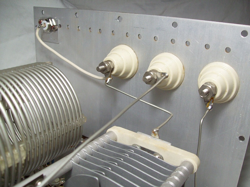
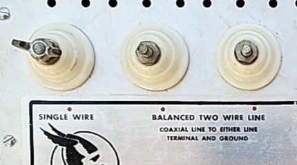 SINGLE WIRE: Connect a single wire transmission line to this feed-thru terminal (see it on pic at right). SINGLE WIRE: Connect a single wire transmission line to this feed-thru terminal (see it on pic at right).
BALANCED TWO WIRE: To balanced feed-thru terminals.
COAXIAL LINE: The inner conductor of the antenna coaxial line should be connected to either of the two BALANCED line terminals, while the other balanced line terminal should be grounded along with the outer conductor of the coaxial cable.
→ COAXIAL LINE I/O MOD: Connecting a coaxial line from an antenna to the balanced terminals can be facilitated by following the layout of the Kilowatt model (see schematic below and pic in gallery above). An SO-239 connector can be added to the rear panel; then the right balanced terminal is internally connected to the SO-239 and the left balanced terminal is externally connected to the GROUND terminal. More info below. |
KILOWATT model, schematic.
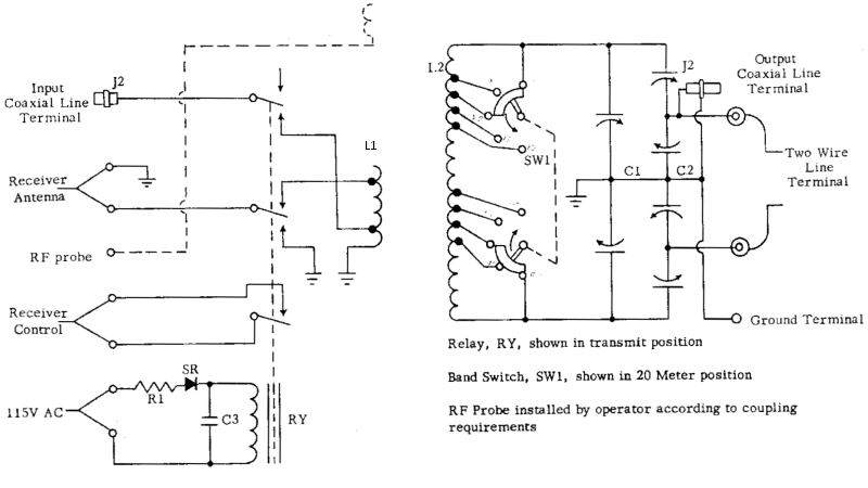 LINE connections:Mouseover image to see the 80 - 40 - 20 meter setup. LINE connections:Mouseover image to see the 80 - 40 - 20 meter setup.
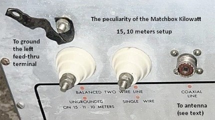 • Kilowatt model has peculiar • Kilowatt model has peculiar I/O connections! I/O connections!
BALANCED TWO WIRE: To balanced feed-thru terminals.
SINGLE WIRE: Connect a single wire transmission line to this feed-thru terminal (shared with balanced two wire lines). The remaining balanced feed-thru terminal must be grounded using the ground terminal above it during operation on 80, 40, and 20 meters, BUT left ungrounded on 15 and 10 meters.
COAXIAL LINE: The coaxial line from the antenna must be connected to the coaxial terminal. The balanced feed-thru terminal thas has the ground connection above (see pic at right) must be grounded using that connection on 80, 40, and 20 meters, BUT left ungrounded on 15 and 10 meters.
• Kilowatt model features relay activation via DC! The switching relay system is off-delayed by means of a fast-make/slow-break
circuit that permits the final amplifier plate voltage to be cut off before the transmitter load is removed thus preventing the final tube from running unloaded when switching to receive mode (the antenna will remain connected for a little longer because the voltage stored in the capacitor keeps the relay activated, even though the voltage that activates it has already stopped). According the manual the delay time is fixed between .15 and .25 of a second.
|
Design:
|
Transformer-type with fixed input impedance of about 50 ohms via link coil. It will vary depending on the impedance reflected(3) by the secondary winding which is connected to an impedance-X antenna, and with variable impedance and frequence adjustment at the output.
→ Primary: Link coil L1.
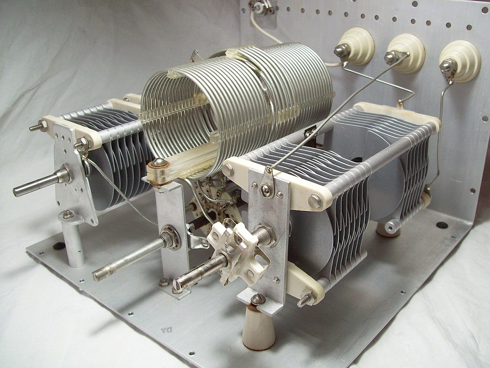
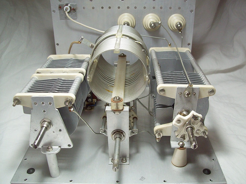
→ Secondary: Parallel-tuned network. L2 taps + dual variable capacitor C1 (its capacitance value varies max/min, standard way) + a dual differential capacitor C2 (very important, see operation at bottom). The proper capacity of C1 and C2 to give the desired impedance match occurs only at one combination of capacities in C1 and C2. C2 operates as a
variable capacitive impedance divider to accomplish matching in the same way that taps on a coil. Therefore, L2 is tuned by:
a) The number of L2 turns that are in operation (switch-selected),
b) The capacitance value adjusted by C1 (10→100 pF),
c) The fixed value of C2 (100 pF, never varies),
d) The load impedance (antenna) combined with the impedance offered by the "C2 variable tap" and the L2-C1 resonance. |
| TUNING knob (C1): |
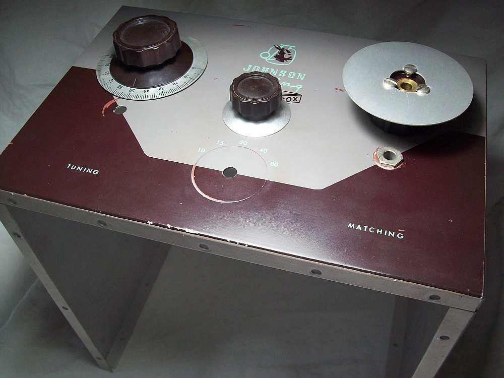
Tunes L2 to the operating frequency.
|
| MATCHING knob (C2): |
Adapts the L2 / C1 impedance to the impedance of the load (transmission line). |
Knob Dial Setting:
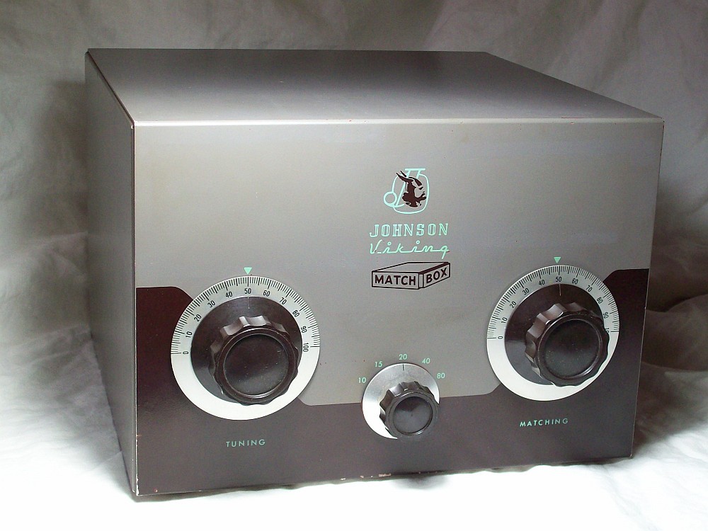
It would be convenient the markings on the adjustment controls corresponded to the degree of opening of the capacitors they control and/or also indicated "what is happening".
|
TUNING knob C1 will show equivalent (parallel to C2) direct indication since, being of the standard variable type, a more closed position means more capacitance ('100', rotor plates up) and a more open position means less capacitance ('0', rotor plates down).
MATCHING knob C2 doesn't follow the same rule, upward-facing rotor plates imply minimum capacitance in series and maximum capacitance in paralell at input terminals; downward-facing rotor plates imply maximum capacitance in series and minimum capacitance in parallel at input terminals. Since series coupling means lower impedance matching and parallel coupling means high impedance matching(4), we can associate these concepts to capacitance numbers.
Thus, when the MATCHING knob C2 is going towards '0', the operator will know that the Matchbox is trying to match a low impedance line; and when the C2 knob is going towards '100' the operator will know that the Matchbox is trying to match a high impedance line.
To achieve this, before placing the Matchbox inside the box:
- 1) Place C1 and C2 rotor plates to the right in symmetrical position, C1→) C2→).
- 2) Since the rotor plates are not cut at 180°, it is recommended to pay attention when adjusting C1 and C2 rotor plates to the right (50% capacitance, see enlarged image showing its shafts marked with a half-capacitance line and rotor plates positioning).
- 3) Both C1 and C2 have capacitor sections of 10 to 100 pF. Mark the end shafts of the capacitors to determine the half-travel position ('50' mark on the knob).
- 4) Set the bandswitch to 20 meters, the knob position pointing up.
Once the Matchbox is inside the box, the line on the shaft indicates the '50' position on the control knob. In this configuration, 0
and 100 on the TUNING knob will indicate a capacitance value (approximate), and 0 and 100 on the MATCHING knob will indicate capacitance insertion level, respectively. The band selector can be installed in the same way as the other
controls, and all of them can be tightened from below. |
REAR PANEL
Control terminal strip (right to left)←: |
1 & 2: Coil of the relay, 115 VAC!
3 & 4: 'Receiver control' contacts, normally closed (receiving mode is default). Used to inject voltage in order to silence the receiver during transmission periods.
5: RF probe, free. It may consist of a short piece of stiff self
supported wire with a small turn on the end to provide loose capacitive coupling to the coupler inductor.
6 & 7: 'Receiver antenna' connection. Terminal 6 is connected to the 300 ohm tab of L1, in receiving mode, terminal 7 is ground. |
T/R relay setting:
Antenna switching between transmit and receive and other functions. |
The Matchbox's relay is set to receive mode by default (relay lever in upper position).
When the relay is in receive mode:
a) RF IN is open cicuit (OFF).
b) Receiver control (3,4) is closed (ON) in order to delete B- voltage.
c) Receiver antenna (6,7) selects the 300 ohm tab on the L1 link.
When the relay is in transmit mode:
a) Relay activation upon transmission (1,2 115 VAC).
b) RF IN selects the 50 ohm tab on the L1 link.
c) Receiver control (3,4) is open (OFF) in order to activate B- voltage.
d) Receiver antenna (6,7) short-circuit receiver antenna terminals to ground. |
| GROUND: |
This terminal should be connected to the ground terminal on the transmitter by means of a large gauge wire. The lead from the transmitter to ground should be as short as possible avoiding any lengths near an odd multiple of quarter wave on the operation frequency. For multi-band operation, ground leads of various lenghts should be installed. |
| RF INPUT from transmitter: |
SO-239 UHF connector. To interconnect a 50-ohm coaxial cable as short as possible between the transmitter and the Matchbox, since the input impedance varies more rapidly with frequency as the length of the line increases. |
| Removal of the mounting chassis (base/rear panel): |
By removing 22 screws, 3 knobs, and sliding back the mounting base and rear panel as if it were a drawer from the front panel/upper & lateral sides. |
Coaxial I/O MOD for 275 (use layout below):
Unbalanced ANT IN (antenna→Matchbox) and RF OUT (TX→Matchbox) connector:
It can be done with option '3-2/4' or '2-3/4'.
• BAL terminal #3 internally connected to an UHF connector. See rear panel in the gallery.
• BAL terminal #2 externally connected to GROUND (#4). See rear panel in the gallery.
3-2/4 uses the lower branch of the coupling network, the one NOT connected to SINGLE WIRE. This mod can be done externally, see an example of that, but using option '2-3/4'. |
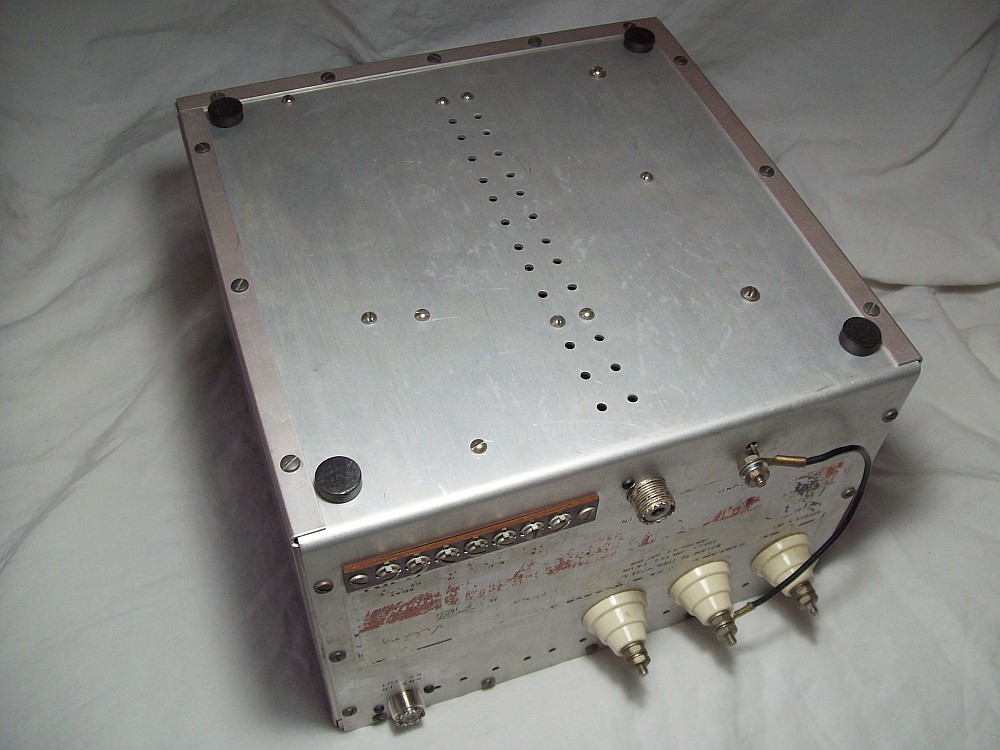
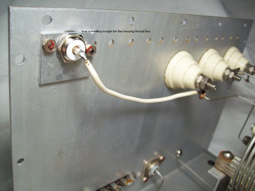
The most common modification on the Matchbox Model 275 was to adapt the Kilowatt model's coaxial cable input for easier connection. This avoided the awkward connection of a coaxial cable to the 'BALANCED TWO WIRE LINE' terminals, but it is still necessary to make the external connection required to ground the balanced terminal located directly above the GROUND terminal.
This particular unit had this modification, but whoever made it didn't pay much attention to the placement of the SO-239 and chose the worst possible spot, the rear panel could not close completely! I had to make to give the location of this connector a, let's say, 'factory-made' appearance (only possible thanks to the Amphenol type 083-875-1002 connector and an adapter plate). Now the rear edge of the box has a margin of less than half one millimeter to prevent the back cover from closing! The revision of the mod can be seen in images 3 and 4 of the gallery at the top of the page. Mods should be carefully considered before being made. |
Matchbox-circuit's theory and Matchbox-device's installation.
The text that follows is an adaptation of the text included in the first Johnson Matchbox manual, omitted in later versions of the manual.
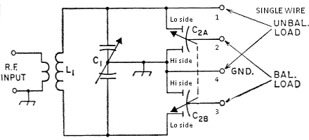 A two wire balanced line is connected to terminals 2 and 3. Capacitor C1 is the tuning capacitor and the four section C2 is the matching capacitor. The paralell resonant circuit consists of L1, C1, and C2; a high impedance will be found to exist across L1, C1, and C2. Since C2 is a dual differential capacitor, the total capacity across the circuit remains constant, but the capacity in C2A related to C2B will vary inversely with rotation (differential operation). C2 is adjusted along with the tuning capacitor C1 to resonate the circuit and also provide the proper division of impedance to match the transmission line and at the same time compensating for any reactance wich may be present at the transmission line terminals.
NOTE: The graph/layout above was found on the internet, I have corrected it to show what happens when C2 is operated, thus activating its function as a "potentiometer". 'Lo side' and 'Hi side' refer to the location of the rotor plates inside the Matchbox, NOT to impedances.
- → Balanced two wire lines should be attached to the 'BALANCED TWO WIRE LINE' terminals.
- → If a coaxial transmission line is used from the antenna, the inner conductor of the coaxial line should be attached to either one of the two balanced line feed-thru terminals, the other balanced feed-thru terminal must be grounded, and the outside conductor of the coaxial line must be connected to that terminal (this is, grounded).
- → A unbalanced single wire antenna or transmision line may be connected to either terminal 1 OR 2 depending upon the impedance at the end of the line: A high impedance unbalanced line should be connected to terminal 1, a low impedance unbalanced line should be connected to terminal 2; terminals 3 and 4 should be connected together.
- → If the transmission line is a single wire and the end of the antenna is
of high impedance, it should be connected to the feed-thru insulator labeled 'SINGLE WIRE'; this will attach the line to the end of the
resonant circuit which is the high resonance point. A single wire with low impedance should be attached to either of the two balanced line feed-thru terminals (2 OR 3) with the remaining balanced line terminal connected to ground (4). So, if terminal 2 is used for low impedance single wire, 3 to ground; if terminal 3 is used for low impedance single wire, 2 to ground.
The "potentiometer" effect:
- • C2A and C2B rotor plates are the "potentiometer taps" connected to the BALANCED load terminals
- • C2A and C2B upper stator plates are grounded, the lower stator plates are connected to the L1's ends, respectively.
- • C2A lower stator plates are connected to the SINGLE WIRE load terminal.
- • C2A and C2B are 10 pF to 100 pF variable capacitors from rotor to upper stator and rotor to lower stator, each.
- • Observing what happens in each of them the "potentiometer effect" can be explained. C1A
and C1B can be considered two potentiometers with one shaft, both select the same tap within the total "resistance value".
- • The graph shows C2A and C2B with rotor plates located at LOWER position. This means MAX capacity IN SERIES and MIN capacity in PARALLEL (low Z coupling) and corresponds to the '0' indication on the knob when adjusted following the 'Knob Dial Setting' above. C2A rotor selects 100 pF from its lower side and 10 pF from its upper side; this means 100 pF in series with one side of the balanced
line and 10 pF in parallel to ground on that side, and the same occurs on the other side of the balanced line (C2B).
- • Now imagine the arrows pointing to GND (ground).
- • C2A and C2B rotor plates are located at UPPER position. This means MIN capacity IN SERIES and MAX capacity in PARALLEL (high Z coupling) and corresponds to the '100' indication on the knob when adjusted following the 'Knob Dial Setting' above. Then C2A rotor selects 100 pF from its upper side and 10 pF from its lower side; this means 10 pF in series with one side of the balanced line and 100 pF to ground on that side; and the same occurs on the other side of the balanced line (C2B).
- • Therefore, different positions of C2 will cause different impedance matching to the line.
|
| |
Controversies around the Johnson Matchbox input link.
1 — As early as 1962, Harry Hooton(5) realized that the Matchbox tuning capability was becoming difficult if a low-pass filter or some kind of SWR meter was inserted into the tuner's input line (where the SWR meter should be inserted(6)). For this reason, in his book "Amateur Radio Antenna Handbook", page 118, he proposed installing a 350 pF variable capacitor in series with
the input link L2 (note it is labeled L1 in the Matchbox).
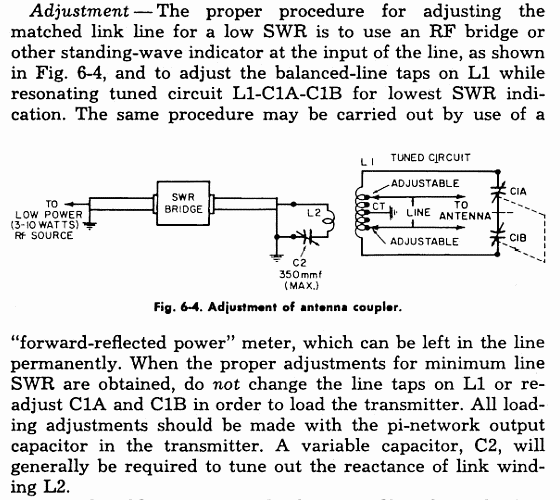
The effect of C2 is to vary the coupling between L2 and L1. This variable capacitor can be installed at either end of L2, but it is more practical to use the cold side of the link. The capacitive reactance of C at its maximum capacity must be the same as the inductive reactance of L2 at the operating frequency; and this happens when the LC network enters at the resonant frequency. When this condition is reached, the total reactance cancels out (=0), the total impedance is reduced to the value of the pure resistance (ohms), and thus the current can be evaluated via Ohm's law. Therefore, when adding the capacitor to the link, the inductance of L2 (link L1 in the Matchbox) may need to be increased(4-a) to reach the above conditions... and this relates to the last mod that was made in #2 (below).
2 — Later, in 1972, William I. Orr describes in his book "Simple Low-Cost Wire Antennas", page 160, an experimental tuner based in the design of the Johnson Matchbox under the name "Universal Antenna Tuner" (note AGAIN the deconceptualization).
Orr also includes a variable capacitor in the cold side of the input link.
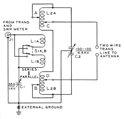 • Note the combined series/parallel input link with a variable capacitor to ground. The series selection is for 3.5 and 7 Mcs bands (e.g. two coils of 6 turns will result in a coil of 12 turns). Parallel selection is for 20, 15, 10 Mcs bands (e.g. two coils of 6 turns will result in a coil of 3 turns). The complete coil (L1 + L2) is = 4 windings of 32, 5, 5, 32 turns... very similar to the Johnson Matchbox, but L1 has double winding here(4-a).
• Looks like was later modified adding specific band selection for L1. On "Adjusting the antenna tuner", page 164, we can read:
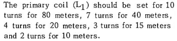
• Text and pics in the book don't show those taps. Schematic shows that there are two operating options for the link: (5 turns in series with another 5) for 3.5 and 7 MHz bands, and (5 turns in parallel with another 5) for 20, 15 and 10 MHz bands.
W. I. Orr, "Universal Antenna Tuner", in his book "Simple Low-Cost Wire Antennas".
Johnson's manuals contained references to the use of that type of antenna tuner compared to the Matchbox tuner.
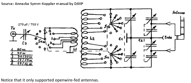
3 — And 10 years later... the Annecke mod... which is in fact an adaptation of the Orr's L1 band selection. Alfred Annecke was a German amateur radio operator that began offering antenna coupler kits in the 1980's in Germany. He based the design of
his symmetric coupling tuner on the original Johnson Matchbox design after realizing the difficulties, and the risk, of using the Johnson Matchbox with
solid-state transceivers (these devices have a fixed 50-ohm output with no output coupling adjustment).
See below the mod that Annecke incorporated to its symmetrical tuner to adjust the input link. It consists of making switched input taps for different bands on L1, and adding in series with the input a 270 pF capacitor (note the similarity to Orr's final mod). The L2 network is a copy of the Johnson Matchbox design.
4 — Why an antenna coupler? Lew McCoy (W1ICP) on transformer-type transmission line tuners: QST, 03-1959, 5 pages.
|
(Monimatch-type SWR Meter + Johnson Matchbox) Worksheet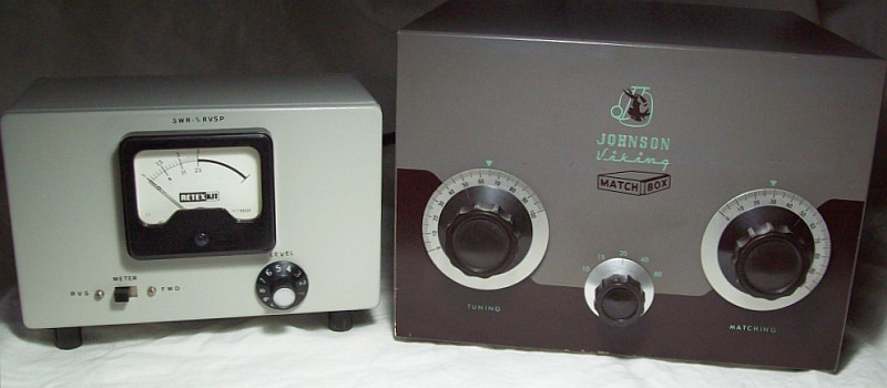
Inline sequence: →Tube transmitter →Retextkit ME-1 SWR meter (Heathkit AM-2/HM-11 type) →Johnson Matchbox →Antenna
| Step |
Instructions IMPORTANT! The "dip" procedures described below are those that were applied to classic tube transmitters. |
| 1 |
Turn the matchbox band selector to the desired operating band. |
| 2 |
Turn the AM-2 function switch to 'FORWARD'. |
| 3 |
Adjust the transmitter final amplifier at low
power in the same operating band. This is noticeable when the plate
current shows a minimal "dip". |
| 4 |
Adjust the AM-2 to full scale indication by operating SENSITIVITY. |
| 5 |
Turn the AM-2 function switch to 'REFLECTED'. If the AM-2 meter reads more than full scale readjust SENSITIVITY to full scale. |
| 6 |
Alternately(*) adjust the matchbox TUNING and MATCHING knobs until the AM-2 meter reads minimum SWR. Keep the transmitter final amplifier in resonance (the "dip" in plate current) while tuning the Matchbox.
(*)To understand this step, check step 5) below. |
| 7 |
When the AM-2 meter indicates minimum SWR, turn the AM-2 FUNCTION switch to 'FORWARD' and if necessary readjust SENSITIVITY to full AM-2 meter scale. |
| 8 |
Turn AM-2 FUNCTION switch to 'REFLECTED' and retune the Matchbox 'TUNING' and 'MATCHING' knobs for minimum SWR. |
| 9 |
Adjust the transmitter output to the desired power (adjusting again the "dip" in plate current). DO NOT attempt to load the final amplifier by changing the Matchbox adjustments. |
| 10 |
Turn AM-2 FUNCTION switch to 'FORWARD' and adjust SENSITIVITY for full scale reading on the AM-2 meter. Return to the
'REFLECTED' position; the meter reads the actual SWR at full power. |
| 11 |
Record the Matchbox 'TUNING' and 'MATCHING' dial settings for future reference. |
| 12 |
The operating frequency may be changed until a maximum SWR of 1.5 is indicated in the AM-2 meter. If SWR increases the matchbox should be readjusted per steps 1 to 10 above. |
Key points to understand the effect of the adjustments
Adjustment of the final π stage of the classic tube transmitter (MOPA design = master oscillator + power amplifier having a final-tube milliammeter on the front panel).
- 1) Antenna LOAD capacitor at maximum capacity (closed). This
capacitor can be considered like a water faucet; when closed, no RF comes out,
the more open it is, the more RF comes out.
- 2) By operating the PLATE capacitor, find the minimum plate current.
- 3) Begin opening the LOAD capacitor; this causes a mismatch that results in an increase in plate current.
- 4) Readjust the PLATE capacitor for minimum current.
- 5) Repeat steps 3 and 4 until there is NO EFFECT on the plate current.
- 6) Having achieved this, the resonant adjustment for maximum output at the operating frequency has been found with the minimum plate current combined with the maximum opening of the LOAD capacitor.
Tuned coupling transmission line circuits.
Tuned coupling ensures the highest selectivity of the transmitted frequency, minimizing the radiation of unwanted frequencies while guaranteeing maximum power transfer. To match a low impedance line, series tuned coupling or 'current feeding' is used; the variable capacitor is placed in series with the line. To match a high impedance line, a parallel tuned coupling or 'voltage feeding' is used; the variable capacitor is placed in parallel with the line.
This is important for understanding the operation of the differential capacitor C2. This type of variable capacitor maintains a constant capacitance value between its stator plates; what varies is the output capacitive impedance due to the position of its rotor plates within the total
capacitive impedance between the stator plates. Therefore, this type of capacitor creates a variable tap, similar to a potentiometer, but instead of adjusting a resistance tap between two poles, it adjusts a capacitive tap between them, resulting in an increased capacitance value inserted in series (thus tending towards low impedance coupling), at the output when the "potentiometer tap" is positioned near the lower pole (ground), and viceversa (capacitance in paralell with the line) regarding the lower pole when the "potentiometer" is positioned near the high pole; that is, the series capacitance decreases and the parallel capacitance increases and viceversa depending on the position of the "potentiometer tap".
Tuned coupling features.
The equality between the inductive reactance XL and capacitive reactance XC at the resonant frequency applies to both series and parallel circuits. In both cases, resonance occurs when the frequency causes the reactances to cancel each other out because they are 180 degrees out of phase is zero at
resonance (current in an inductor lags 90º and in a capacitor leads 90º); the LC circuit will only have the ohmic resistance of the wire.
However, the circuit's behavior changes drastically at its terminals depending on the resonant circuit is series or parallel.
→ In a series circuit the total impedance becomes minimal; it is limited only by the internal resistance. The circuit allows maximum current flow at the resonant frequency.
→ In a parallel circuit the total impedance becomes maximal due to the 'tank effect' of its own resonance and the 'flywheel effect' of the plate circuit. Unlike the series LC circuit, the parallel LC circuit has a life of its own. The circuit allows minimal current flow at the resonant frequency, preventing the full current from flowing from the source. The power supply only needs to provide the current necessary to cover energy losses (such as the internal resistance of the cable or inductor). Since this external current is almost zero, by Ohm's law Z=V/I dividing the voltage by a current close to zero results in an incredibly high impedance value. That is, although the total reactance in a resonant LC circuit = "AC ohms" = 0, because ZL and ZC are in parallel, this cancellation does not create a short circuit. Instead, it causes a huge oscillating current to circulate within the LC circuit, drastically reducing the current the source needs to supply. This results in maximum impedance by creating a local power amplification effect known as "the tank effect"; this is something very important to keep in mind in order to understand the "dip" produced in steps 3, 6, and 9, in which the "tank circuit" of the transmitter's power tube plate resonates in parallel!!! The
goal is for the reactance of the "tank circuit" to cancel the reactance of the line, thus generating a purely resistive load.
 Precautions: Precautions:
- — Monitoring the loading/matching operation with an SWR meter is absolutely mandatory; perhaps that's why E.F. Johnson Co. included it in the models ending in '-3' years later; however, using a Monimatch-type SWR meter gives the same result. Refer to the image above showing a Monimatch-type SWR meter + Johnson Matchbox combo; and by clicking on the top left floating image, you will see detailed info about Monimatch-type SWR meters.
- — Observe the Matchbox input: It's a 2-turn coil for 50 ohms, and this coil is the output load of a transmitter. There's no capacitor in series, so for DC it's a short circuit, and for AC it's a resistance value that depends on the frequency. Now let's apply those two turns to the 1st schematic in the "designed to be connected to" paragraph above. This corresponds to a closed circuit from a secondary to a primary, and by design, it's initially inter-balanced. Now let's apply the two turns to the 2nd schematic. They are in parallel with C16, and since they are in series with L4, an AC (RF) short circuit can never occur. It is mandatory to ensure that the link has sufficient impedance (let's understand "resistance") at the frequency in use; otherwise, there is a risk of short-circuiting the transmitter. This "resistance" is created by the tank resonance of the primary L4 with the secondary L2 of the Matchbox (coupled via the link) regarding to the first schematic and by series resonance regarding to the second schematic, but... what happens when using a solid-state transmitter/transceiver...? If the load impedance value is insufficient, the output stage would be exposed to a certain level of overload and would overheat, resulting in a lack of performance, and there won't be any red-hot coloration; the transistor will act as a fuse if it does not have a protection circuit.
- — Be careful when using the 275-Matchbox with the transmitter at maximum power and high SWR. It is very important to avoid overheating the winding to prevent damage to the self-supporting structure and the separation between turns, as it is made of plastic material; the band selector could also be damaged. In the Kilowatt model, the self-supporting coil structure is not sensitive to the effects of heating because it is made of a non-plastic material; also the bandswitch is special for this model. It would be a real shame to damage such a well-made device due to a lack of awareness of its limitations; BTW, this is something the manual doesn't clarify... but 1953's Hams didn't need much clarifications either; in those days Ham Radio was a hobby for people interested in electronic knowledge.
- — IMHO wouldn't recommend using the Matchbox with modern solid-state outputs; it may involve risks and, in its most favorable aspect, difficulty or impossibility of coupling. See "Controversies around the Johnson Matchbox input link" above.
|
|
Citations:
- (1) QST Nov-1955; Pi and Pi-L Design Curves by WØSRL RC Miedke, engineer at Collins Radio.
- (2) The 250-37 accessory is of this type, Johnson calls it 'Directional Coupler'. It has the SAME design as the Heathkit AM-2 (in fact a Lew McCoy design, refer to the AM-2 related link on the side). The great advantage of the SWR meter Monimatch-type is that it does NOT disturb the transmission line, the drawback is that it is sensitive to frequency; the higher the frequency, the more sensitive it becomes. BTW, the famous Bird is also of the Monimatch type; it disguises the sensitivity/frequency issue by using many "bottle stoppers" for different power levels.
- (3) The reflected impedance effect is the phenomenon by which the impedance (resistance + reactance) of a load connected to the secondary winding of a transformer is 'transferred-reflected' back to the primary circuit. The load impedance "reflects" back to the source side scaled by the transformation ratio. Therefore, in a 1:1 transformer, short-circuiting the secondary is equivalent to short-circuiting the primary; and short-circuiting a section of the secondary is equivalent to short-circuiting the equivalent of that section in the primary. E.G.; a 4:1 balun connected to a 300 ohm antenna "short-circuits" 1/4 of the antenna impedance, thus giving 75 ohms to the transmission line. When the Matchbox is connected to an output line of a tube transmitter, L1 can be adapted ('matched') by adjusting the transmitter's output circuit, but when it is connected to a modern transistorized transmitter this adjustment is impossible since there is no such output circuit in the transmitter; L1 can only be adjusted by tweaking L2 and only to a certain extent; furthermore this adjustment does not guarantee that L2 presents the appropriate impedance to match a 'X' antenna. To transfer the maximum amount of power from a source to a load, their impedances must match; if they do not, an impedance transformation network (balun, transformer, etc.) should be used to adapt the load impedance to match the source impedance.
- (4) The Radio Amateur's Handbook, 1967 ed, page 359, fig 13-12, 'Coupling the Transmitter to the Line'. (4-a) Page 155/156, fig 6-11 C. Inductive-link coupling; flat frequency transmission lines. Link-coupling example: page 162, fig 6-19, an impedance-transforming layout that creates a transmission line (the link) with wide (flat) frequency response due to its low impedance.
- (5) Harry Hooton was one of the best popularizers on electronics for Hams, often surpassing better-known figures. Surprisingly, remained relatively unknown, perhaps because he belonged to the generation before the 1940s. Hooton is one of the favorite sources of technical knowledge for the author of this page.
- (6) On the line from the transmitter output to the Matchbox input (which will in fact be a very short line). If installed at the output of the Matchbox, the SWR meter will indicate SWR on the line from the output of the Matchbox to the antenna feedpoint (in fact, the REAL antenna line; any mismatch there must be resolved by working on the antenna or using baluns). But due the transformer-type design, the Matchbox MAY work on adapting ("matching") the antenna feedpoint; this will ONLY happen when the combination of the antenna impedance load value AND the adjusted network impedance
inside the Matchbox (in fact, two impedances in parallel) is correct FOR the antenna and also reflects 50 ohms (or the impedance that the π circuit can adjust in the case of a tube transmitter) at the Matchbox input (L1).
|
Conclusion:
The Johnson Matchbox is a device designed in 1953 for the equipment of that era, in which transistors (invented in 1947) were completely out of the picture, therefore the use of the Johnson Matchbox applies mainly in combination with tube outputs (tuned link or π output) and with a "do not disturb the transmission line"-type SWR meter(2) at its input. To do this, Johnson provides a Monimatch-type SWR meter under the name "Directional Coupler", which may come integrated with the Matchbox depending on model. The question to ask before using the matchbox is: What does the L1 input link expect to "see"? If the answer is: "A 50 ohm impedance direct coupling" (meaning modern solid-state gear), its use is not initially recommended because the Matchbox's input link L1 needs to be coupled by the transmitter's Pi/Tank output circuit; if this does not exist, its coupling will only depend on providing an approximation of the reflected impedance(3) to the value of 50 ohms. What is impressive about the Matchbox is the high level of manufacturing quality, which appears to be a quality inherited from the manufacture of electronic equipment during World War II; and what is surprising is the lack of info about the design of this line coupler in the manual; and that is precisely what motivated me to include detailed info on this page.

|
|