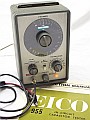
| The Eico 955 In-Circuit Capacitor Tester
is an instrument that allows the user to check capacitors in-circuit or,
of course, out-of-circuit. As similar instruments like Heathkits CT-1 and
IT-22, it will disclose open, shorted, or intermittent capacitors, but
in addition to these models, it can detect SHORTED electrolytics and can
make CAPACITY measurements even when the shunting resistance is low. Due
this characteristic this instrument can check the old filter capacitors
that are present in vintage radio power supplies. Another remarkable feature
is the low test voltage (6 volts), this permits practically to check all
capacitors commonly encountered in old transistor equipment. |
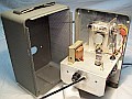
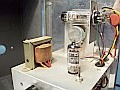
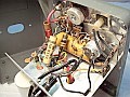
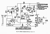
EICO model 955 pics & Schematic + How It Works?
 |
 |
 |
 |
 |
Using the Eico 955.
A three-position TEST switch is employed. At left "SHORT" for the short
test, center is "CAPACITY" for the measurement test, and at right "OPEN"
for the open test. This instrument is more easy to use than the Heathkit
IT-22
on short and open tests due it offers an affirmative indicator for the
"SHORT?" and "OPEN?" questions, so when the eye closes the answer always
is "YES, there is a SHORT/OPEN circuit" respectively. The IT-22 (and CT-1)
"OK" responses are "NO SHORT circuit" when the indicator closes and "NO
OPEN circuit" when remains closed.
Before testing, however, make sure the power is off in the equipment
being tested.
Set RC RANGE to 7-INF, rotate RC BALANCE from OFF to INF, and allow
the instrument time to warm up. Switch TEST to "OPEN" or "SHORT" position
and clip the test leads across the capacitor to be checked: Closed bars
always indicate the condition tested, and a fluttering bars always indicate
an intermittent capacitor.
The limits of CAPACITY measurement are from 0.1 to 50 µF using
Wien Bridge with a unique shunt resistance balancing provision that allows
in-circuit measurement even when the shunting resistance is comparatively
low. The reading point is just above the center of the indicator bar-pattern.
It should also be remembered the following...
-
ELECTROLYTIC or BIG capacitors greater than 200 µF may give false
short tests as tube bars will show an increasingly small gap due its low
impedance at 50/60 cps.
-
TUBULAR ELECTROLYTICS or SMALL capacitors less than 15 pF may give false
open tests as tube bars will show an increasingly small gap due its high
capacitance at 22MHz.
-
On IN-CIRCUIT testings may occur false results due stray capacities or
if the capacitor to be tested is not sufficiently isolated from its associated
components.
|
Specifications and Operation
| SHORT test |
-Reliable up to 2000 µF, or with
a shunt resistance as low as 1 ohm (*1).
-All tipes of capacitors.
-Test frecuency: 50-60 cycles (AC line).
-Test voltage: 6 volts AC. |
-Totally closed bars indicate a SHORTED
capacitor or an impedance less than 1 ohm.
-Partially closed bars indicate an impedance between 1 ohm and 10 ohms.
-Fluttering indicates intermittency. |
| OPEN test |
-15 pF to infinity, or with a shunt resistance as
low as 35 ohms for capacitors above 100 pF.
-All tipes of capacitors.
-Test frecuency: 22 Mcs (HF oscillator).
-Test voltage: Very low (RF current). |
-Totally closed bars indicate an OPEN capacitor or
a capacitance less than 15 pF.
-Fluttering indicates intermittency. |
CAPACITY
measurement |
-From 0.1 to 50 µF (*2).
-RC BALANCE control calibrated in RC product (shunt resistance in Kohms
X capacitance in µF) in two ranges, 0.6 to 10.5 and 7
to infinity, selected by the RC RANGE switch.
-All tipes of capacitors.
-Test frecuency: 50-60 cycles (AC line).
-Test voltage: 6 volts AC. |
-Set the RC RANGE switch to 7-INF.
-Set the RC BALANCE control to INF.
-Rotate the DIAL until you see the smallest gap.
-Rotate RC BALANCE counterclockwise until the gap becomes a little
smaller, stop and immediately correct the DIAL for the smallest gap, and
then close the gap partially by rotating RC BALANCE again.
-Repeat this procedure until a complete closure of the gap is achieved.
This may cause overlapping (*3).
-Read the DIAL but note: The point of balance should be approached
always by rotating the RC BALANCE control counterclockwise and without
going beyond the point of best balance (*4). |
(*1) This instrument is not designed to
detect leakage, the existence or importance of any leakage must be checked
disconnecting one end of the capacitor and using a condenser checker, like
the C-3.
(*2) This instrument will not check accurately in-circuit capacitors
which are shunted by a resistance of less than 35 ohm, or capacitor-resistance
parallel combinations having an RC product less than 1.0. Either or both
conditions exclude the possibility of in-circuit measurement, as may cause
false indication. The best thing to do in these cases is to disconnect
one end of the capacitor and measure it effectively out-of-circuit, or
after a part of the parallel circuit is disconnected, so as to bring the
parallel resistance to some higher value, whichever is easier. To determine
the value of the parallel resistance, a check with an ohmmeter is advised
rather than relying on the schematic values.
(*3) Overlapping appears as a bright line at the bar closure point,
the brightness of the line increasing with the degree of overlapping.
(*4) When balance can not be achieved at the 7-INF position of the
RC RANGE switch, and it is necessary to go to lower values of RC, the procedure
is the same described above, but with the RC RANGE switch at the .6-10.5
position. If the RC product is between 7 and 10 on in-circuit measurement,
use the .6-10.5 position, but in the same circumstances on out-of-circuit
measurement use the 7-INF position. |
Tricks & Mods
Tech Notes:
For "normal" use the RC RANGE switch must be positioned on 7-INF and RC
BALANCE rotated clockwise to INF position.
It is mandatory to adjust an minimal gap in the indicator tube bars using the LINE ADJ control. This control
determines the closed bars gap, and this gap may not be the same when the
TEST switch is positioned for CAPACITY or for SHORT/OPEN. This control
should be adjusted so that the green bars of the indicator tube close together
at the centre without overlapping for each test.
Closed bars (BAD capacitor) indicates an impedance of less than 1 ohm (little
resistance at 50/60 Hz) in the SHORT test, or a capacitance of less than
15 pF (much resistance at 22 MHz) in the OPEN test.
The length of the test lead used is the sum of 42" RG-58A/U coaxial + 5"
for the Red and Black cables which end in a cocodrile clip each. Total
length in centimeters: 106,68 cm RG-58A/U + 12,70 cm Red & Black cables
= 119,38 cms. This length has to be exact since it is part of the tuned
open test circuit (although a small error is permissible since the "Q"
of the circuit is not critical), and represents a quarter wave-length line
for the frecuency of oscillation (about 22 Mcs).
Usual TLC:
- Replace leaky paper capacitors first. Original C3 (2 µF) Wien Bridge paper capacitor (reference value
for the bridge) must be replaced due aging. Leakage in this capacitor will cause bad readings on the CAPACITY
RANGE. Also, original C7 (.05 µF) isolating paper capacitor must be replaced
for the same reason. Malfunction or leakage in this capacitor will cause the instrument
become inoperative.
- Consider replacing the old and bulky 75-MC1F connector by a BNC.
After that, retune a bit the oscillator coil using a screwdriver.
- Cleaning, of course.
|

|
