|
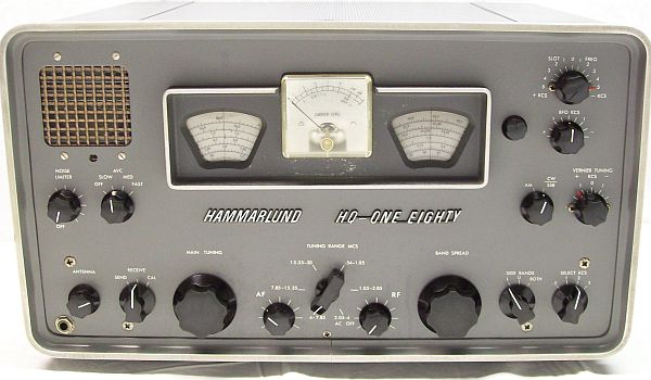
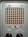
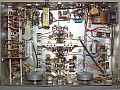
Hammarlund HQ-180, the top model for the HQ line. Same dimensions of
models HQ-145 and HQ-160, companion of the small case models
HQ-100, HQ-105TR, HQ-110, but unlike these, and together with model HQ-170,
it is a totally redesigned model for SSB reception.
Introduced in 1959, it is equipped with 18 tubes (17 model A), covers all frequencies from 540
Kcs to 30 Mcs and has bandspreads for Ham bands of 80, 40, 20, 15 and 10
meters of wavelength. Triple conversion receiver: double on the
160, 80, and 40 meter bands, triple on the 20, 15, and 10 meter bands.
Three intermediate frequencies (1st IF at 3035 Kcs, 2nd IF at 455 Kcs,
3rd IF at 60 Kcs). The 1st IF stage only works on triple conversion, it includes a
crystal filter whose output is injected into a converter that generates
the 2nd IF. On double conversion ranges the first mixer directly generates
the 2nd IF, 455 kcs, that is injected into a gate
amplifier, its output is connected directly to the 2nd IF chain.
On both cases signal is injected into the mixer that generates the 3rd
IF, the mixing tube and its LO (that can be adjusted ± 3 Kcs on
panel) conforms the VERNIER
TUNING, which is a sideband fine tuning device especially for SSB.
Is in this IF chain (60 Kcs) where is located the sideband tuning system
and the selectivity circuitry, this circuit has a Clapp-type
BFO, double-triode product detector, followed by an adjustable
noise limiter.
To aid about interfering signals a slot
filter covers the whole 455 Kcs IF output channel (± 5 Kcs),
and whose frequency and depth can be adjusted on the front panel, but,
as is usual in this circuits, it is very effective for carrier interference
(or CW), but much less effective for modulated signals.
Operation with this receiver can be classified as excellent on sensitivity and very
good on signal-to-noise ratio. Very good selectable selectivity steps,
easy tuning on SSB either by sideband selection or without selecting
sidebands, good audio, and remarkable stability after a short warm-up time
that depends on the selected band (at higher frequencies more warm-up time
is required). As usual on the Armstrong-type receivers (LO in 1st conversion -
mixer stage) some drift always exists, especially on higher bands, and due
the long frequency covering that the high bands have, frequency readout
accuracy gets worse as frequency increases, that's why these radios should
have a dual-frequency calibrator installed from scratch.
Modes & Operating Procedures
→ AM
- 1) Function switch to "AM", AVC to "FAST", VERNIER TUNING to "0", SIDE BANDS to "BOTH", and SELECT KCS to "3",
NOISE LIMITER "OFF". Important! SLOT FREQ standard position is "+ 5 KCS" or "- 5 KCS", NOT "0".
- 2) Tune signal until maximum S-Meter indication is achieved.
|
→ FM (voice-range ONLY)
- 1) SIDE BANDS at "L" or "U", the rest as above.
Test best sideband because frequency response skirts are not symmetrical.
- 2) Slowly tune signal to achieve the best reception.
|
→ SSB
- 1) Start with AVC to
"MED", switch to "CW/SSB" and set BFO KCS at center (HQ-180),
select SSB (HQ-180A), VERNIER TUNING to +/- "1.5" depending on received
sideband, SIDE BANDS to "BOTH" and SELECT KCS to "3".
- 2) Tune signal until maximum
inteligibility is achieved, it is very easy if the received sideband is correct
and the SSB system is adjusted correctly. If the signal cannot become
inteligible change VERNIER TUNING to the opposite side (this occurs usually
on CB where does not exist a pre-defined sideband).
- 3) Switch SIDE BANDS to
"L" or "U" depending on sideband detected. Interference will be down and signal
will be up. Inverse selection causes signal disappearance (or almost, only
strong signals will be heard).
- 4) This is the fast and modern
procedure. Hammarlund describes a procedure using the S-meter and tweaking
continuously the VERNIER TUNING, it leads to go misadjusting the band centering,
these procedure is slow, outdated.
|
→ CW
- 1) Set AVC to "FAST", VERNIER TUNING to "0", SIDE
BANDS to "BOTH" and SELEC KCS to ".5" or "1", BFO KCS at center.
- 2) Switch to "CW/SSB" (HQ-180) or "SSB" (HQ-180A) to tune the
pulsating carrier at zero beat (S-Meter needle oscillates with no sound).
- 3) HQ-180: Adjust BFO KCS to desired
CW pitch. HQ-180A: Switch to CW, a CW pitch of 500 cs is automatically selected.
- 4) When the narrowest bandwidth
is selected (".5") an interfering signal can be removed, but a loss of gain may be noticed.
- 5) SLOT FREQ correctly tuned with the
Slot Depth adjust (control located behind panel, accessible by opening the upper gate)
at maximun will eliminate an adjacent CW signal, but not an AM signal.
|
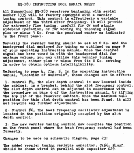
Since initial model of 1959, the main modification was to move the SLOT DEPTH adjustment
to the inside with the intention of placing the so-called VERNIER TUNING knob on panel
(that is correctly labeled as PASSBAND TUNING on the HC-10); an excellent idea as the SLOT DEPTH control should always be set to the maximum depth,
then it can stay like this forever. This control on panel is unnecessary (and this applies to all Hammarlund models that have this control on panel),
but the VERNIER TUNING control on panel is absolutely necessary in order to pre-adjust sidebands optimally.
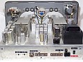
Hammarlund offered a modification kit for the receivers of first manufacture, the Passband Tuning (Vernier Tuning) control was incorporated on panel beginning serial #1335 (MouseOver right pic to see the mod-kit #42188 installed).
 |
|
Although Hammarlund says "normally the vernier tuning should be set at 0 Kc", this is contradictory with "moving the incoming signal plus or minus 3 Kc from the passband center" considering that "U" and "L" positions of the IF chain will select only one side band, thus it is mandatory the VERNIER TUNING selects also that side band. Tuning with vernier at center the incoming signal will not match with the internal "U" or "L" IF chain adjust, it only will match when "BOTH" is selected (that means "both sides", aka "center"). |
The model A starts in 1963 as an extension of the main model HQ-180XE.
It features solid state power supply and a separate always-connected filament
transformer that supplies voltage to the heaters of the high mixer tubes (V2 &
V12) in order to get more frequency stability and reduce initial warm-up
drift. These tubes runs 24/7, IMO it is a bizarre idea, especially when
Hammarlund says "this transformer also supplies the system socket"...
adding sporadic loads to a line intended to improve stability is not precisely a good idea.
Plastic dust covers for main and bandspread tandem capacitors were removed in model A due:
"after extensive enviromental testing, it was found that under certain
conditions the plastic dust covers served very little useful purpose and
in some cases caused system degradation". "Certain conditions" it's
a vague concept that does not give any information, the only thing for sure
is that plastic covers add some capacity to tandems. Tube shields for V1, V4,
V6, V7, V10, V16, and V18 were also removed due: "it was found the tubes have longer life
with the tube shields removed"; yes, the tubes have longer life, but
now they are exposed to magnetic fields and possible coupling. As the model
evolves changes may be made, but changes not always represent real improvements,
sometimes it is necessary to go back; an example of this: starting with
model A, C124 was wired differently, but then was indicated that it
should be wired in the same way as in model non A.
Model A introduces individualized SSB and CW positions, BFO frequency is fixed
internally, it only can de adjusted acting on the BFO coil, thus the BFO
knob is not operative on SSB, it is operative only on CW. A trick to get
the BFO knob to work on SSB is to select CW mode, it works, but note that in this model, when in CW mode,
the center (zero) position of the BFO does not match in frequency with the IF at center
since the CW position automatically gives CW tone with BFO at center.
Being that the BFO KCS control is disabled on the panel in SSB mode, this allows it to be specifically tuned for CW mode
thus customizing the CW tone, thereafter it can left permanently in that position.
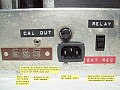
Model A has on the rear a "system socket" that allows to connect additional gear,
also this model adds the option of plugging the radio to a 230 VAC mains besides 115,
this is of great interest to European users.
Final model is the HQ-180AX which includes from scratch into
the hole provided for installing accesories (usually contains a clock timer) a small
black panel which allows to install crystals of pre-calculated frequency in order to work on fixed channels, this panel constitutes an XLO that replaces the LO of the first mixer, it NOT extends the tuning range as many understand confused
by the Collins spreading system. In fact this xtal panel is useless nowadays, and probably improbable to put into operation because these crystals are not standard, you need to calculate the value corresponding to the desired reception frequencies and order them (it also happens that ordering custom crystals can be quite difficult); so better to install the clock or a speaker. The HQ-180AX was manufactured until 1972.
|