Info about this model 's capacitors.
There are NO waxed paper capacitors in this model, and the existing electrolytic filter capacitors are well sized and of good quality; thus if the electrolytics have not dried out due bad location in the chassis or sealing failure (rare), or have not become corrupted due to poor build quality (cheap mfg), THERE IS NO NEED TO REPLACE THEM. This model does not need the application of any "capacitor replacement kit", you would be spending money in vain. BTW, not all, but many of these kits take advantage of the CLICHE belief that the electrolytic capacitors always need to be replaced, this is simply not true, the cliche only holds true for waxed paper capacitors.
Electrolytic capacitors that have NOT experienced overvoltage or overheating are generally in very good condition, but are not YET usable due to depolarization, as it happens when newly manufactured (and before being polarized by the manufacturer). It is the user who damages the electrolytics when plugging in the device without taking into account this behavior, that is, the user causes the failure at that moment. There is no prior failure since depolarization is not a failure, it is a consequence of the elapsed time. It is disturbing to see that good vintage components go to waste because of a successful cliche, or for ignoring the risks associated with connecting a device that has been in storage for a long time. The consequence is that the original appearance of a device is compromised by totally unnecessary "repairs". I'm posting this warning because it's really disappointing that electronics hobbyists mistake normal behavior for a component failure (or cause the failure themselves).
When depolarized, an electrolytic capacitor is not a capacitor, it is a low-value resistor, but this does't mean mandatory replacement. The thing is: Just like a battery discharges over time, an electrolytic capacitor DEPOLARIZES over time; ALL electrolytics, old and new. This means that before reusing these capacitors after a long time in storage a polarization protocol must be performed. It basically consists of starting the device at reduced voltage, letting time pass, raising the voltage and repeating; a "rinse'n repeat process" until the capacitors no longer heat up. The prize is that it is possible to respect the original design without the need for additional spending, the drawback is that if the capacitor has not been used for many years the process can take many hours, but this should not be a problem for an amateur. See an example of the reforming process on the 75A-4's capacitors page.
About off-tolerance resistors: High impedance electronics, such as tube electronics, are usually very forgiving of component values. Barring large differences or values in critical circuits (e.g. bias), it will normally NOT be necessary to replace vintage resistors.
Mods?
On vintage equipment be conservative is mandatory, do not expect perfection
nor seeking perfection. An alignment should only be undertaken if there
is a specific symptom that causes annoying issues (e.g. incorrect dial
marking, evidence of loss of gain, etc.) and a repair should only be undertaken
if there is an evident issue, or for to prevent a malfunction that will
increase with use. Unnecessary fiddling can damage threads of coil cores
or wear down coil grooves. Tubes generally last for decades and only the
problematic tube should be replaced, tube replacement may cause misalignment;
a good example is the LO tube, dial alignment is mandatory if it is replaced.
Resistors usually are very good. Good quality capacitors (all except of waxed paper)
last almost forever even in bad environmental conditions, same for electrolytics,
if they are not damaged by the voltage and have not dried can be reformed.
Replacing components "by default" does nothing important and
the receiver's authenticity appearance is degraded.
An HQ-180 needs to have the SSB system very well adjusted, do not try to adjust it if you do not understand how it works, there are also errors and "lapses" in the manuals. It may be ridiculous to say, but it seems that Hammarlund didn't know exactly how his SSB system worked [Did the designer no longer work on the company? Was the design an external order?]. Helping not to make mistakes is one of the purposes of this pages. Since the Hammarlund's SSB system is unusual, many owners of these radios "adjust" it based on the more common SSB system, this makes it worse, and hence the usual complaint: Audio response.
BFO frequency at center must exactly match the "AM's heterodyned IF" of the receiver, this center should correspond with the heterodyne value of the previous mid-frequency mixer, whose output may not be the exact 455 Kcs value from the schematic, the centers of the SSB channels (USB/LSB) must exactly match the centers of the passband tuning sides, those are the keys. This "transfer of centers" is what makes the system critical. When an HQ-180 has "muddy" or "distorted audio" the audio stage is not usually guilty, what happens is the IF bandpass does not match with the bandpass of the adjustable passband tuning circuit (vernier tuning). By "improving" the audio section, the only thing that will be achieved is to add a wrongly configured stage in order to correct a wrongly adjusted stage. Also nor should we forget that the audio from a true communications receiver can never be as good as the audio from a home appliance, if it is, it is not a communications receiver.
About this, there is a typical modification of this receiver who has gone to solve the effect without analyzing the cause and, unfortunately, has become very popular: Deleting feedback in the audio stage. The Williamson-style audio feedback included in the audio stage (pompously called in the manuals "exclusive Hammarlund auto-response circuit") can never cause distortion, as it is precisely designed to eliminate distortion and compensate for the frequency response caused by the output transformer's response curve. This feedback circuit is initially aperiodic, frequency correction is only determined by the frequency response of the output transformer depending on the power applied to the audio stage (the signal level applied to an output transformer affects its response curve, the Williamson circuit tries to correct this). If it is removed, it will simply produce a response that is predominantly midtone. Deleting feedback is interpreted as a solution to the distorted/muddy audio problem, but the source of the problem is not the audio stage, the source of the problem is bad SSB demodulation configuration, followed by user mishandling of some knobs. Hammarlund auto-response circuit") can never cause distortion, as it is precisely designed to eliminate distortion and compensate for the frequency response caused by the output transformer's response curve. This feedback circuit is initially aperiodic, frequency correction is only determined by the frequency response of the output transformer depending on the power applied to the audio stage (the signal level applied to an output transformer affects its response curve, the Williamson circuit tries to correct this). If it is removed, it will simply produce a response that is predominantly midtone. Deleting feedback is interpreted as a solution to the distorted/muddy audio problem, but the source of the problem is not the audio stage, the source of the problem is bad SSB demodulation configuration, followed by user mishandling of some knobs.
This receiver does not need improvements, just be checked. The HQ-180 is a high-end model, it is not perfect of course, but making bizarre mods in this type of receivers the only thing that is achieved is to improve a bit on something at the expense of losing original features in the rest, thus introducing new problems. To check older equipment, you can use the same devices that were used at the same era as the equipment being tested, it is not at all necessary to have modern equipment. To review an HQ-180 you can use test equipment of similar category and age, a URM-25 for example, or even simpler equipment if a frequency counter can be connected to its output. The old test equipment must have been thoroughly checked of course.
The touch ups in this unit have been the following:
- The oscillator coils of the 1st mixer were retouched in order to get accurate* dial reading as the
MAIN TUNING hairline cannot be adjusted in this model. /* Within what fits taking into account manufacturer and era.
- T28 (BFO KCS coil) was adjusted to the correct frequency (the IF peak at "L" and ".5").
- L4 (the VERNIER TUNING oscillator coil) was adjusted to maximum IF mixing output at "0".
- The pointer-type ANTENNA knob was replaced by a normal knob because this type is more precise on handling.
- The R4 10 ohm neutralizing resistor was replaced by a 100 ohm resistor in order to avoid a self-oscillating point when rotating the ANTENNA control with no antenna load connected. A receiver must be stable in all conditions.
- For my particular taste the HQ-180 has poor AGC threshold performance
selecting AM-FAST, and some lack of AGC attack under strong signals selecting SSB-SLOW;
consequence: AVC options need to be "SSBized". The 1 Mohm resistor (R23) in the AGC line
was replaced by a 100 Kohm resistor for better (fast) reaction to
an incoming SSB signal, and to improve slow AGC release the value of
C131
(.100 µF) was increased up to .220 µF. Time constants for SLOW and MED
positions have been modified, this implies changes in resistor values, also for S-Meter respective zero positions.
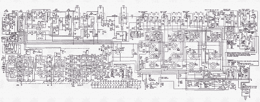
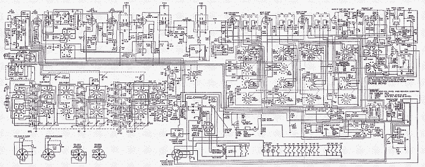
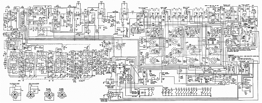
| HQ-180 series 52787-1 manual, page 32 (original schematic has 8 errors in component labeling, fixed below). |
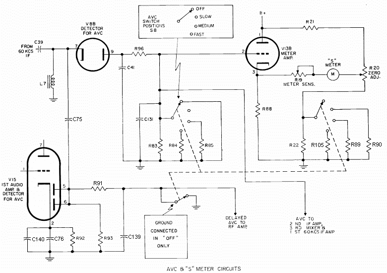 |
• Change: new value (previous value) →
R23: 100 Kohm (1 Mohm, AGC line)
Setting procedure:
R20 adjusted at S0 in OFF position, RF min.
R19 at S9 with 50 µV antenna input, RF max.
|
AVC time constants section.
Selects a time constant in order to manage received signal.
R85: 150 Kohm (47 Kohm)
R84: 1,500 Kohm (470 Kohm)
C131: 0.220 µF (0.100 µF) |
"S" meter common zero section.
Equalizes the effect of the automatic bias entered by the time constant selected.
R90: 2,700 ohm (3,600 ohm)
R89: 3,600 ohm (6,200 ohm), old R90 relocated
R105: 6,200 ohm (11,000 ohm), old R89 relocated |
| • This
simple modification manages better the signal dynamic range, thus
increases reception comfort, and reduces noise limiter distortion.
You only need 4 resistors and 1 capacitor; these changes are fully
compatible with AM performance. |
- A .010 µF capacitor (C158, logged on an addendum sheet for model A) was installed from pin 7 of V18 (455 Kc IF gate) to ground. This is mandatory if you want to avoid an annoying "click" rotating the RF control, this capacitor was never included (updated) in the schematic diagram.
- Since the Telechron Clock Timer is useless in Europe (american version, 60 Hz base-time, in Europe is 50 Hz), a mid-range HI-FI speaker was installed in its place, but due to the amount of audio interference from digital home appliances, I thought it was more practical to install something that filters out those interferences. A 3" cheap speaker is the best solution due to bad response curve, in this application the worst is the best. All of these cheap and bad quality speakers have a pronounced response curve that limits the usable frequencies (200 cs to 3 Kc), so they are perfect for this application, in fact these type of speakers are cheap audio filters. Also important is that this speaker is classic in style, having the usual 4 large mounting eyelets, allowing integrated mounting of a switch in one of them. Everything has been done taking advantage of the same panel holes for the Telechron clock timer, but the clock timer mounting holes are off-center from the main hole, it is necessary to align the speaker to the left with pressure clamps (see details on next page). This mini-switch is operated through the panel hole provided to operate the clock timer. Although the switch is recessed, the hole is large enough to allow full movement of the lever. This switch allows to select the internal speaker or any other external speaker connected to the SPKR terminals on the back. BTW & IMHO, these type of mods must be made thinking about how the manufacturer would have done it, thus respecting the original aesthetics, avoiding permanent damage whenever possible; any aesthetic or electronic redesign of older equipment should be in keeping with the era as much as possible. The use of this small speaker automatically provides human-voice audio response, it acts as an "electro-mechanical audio-filter". This simple solution will make operation more enjoyable by cutting low and high resonances which will help greatly on reducing background noise. With this internal speaker added, and the standard external loudspeaker, this HQ-180 has two different audio responses. Dry transfer letters SPK/MON (speaker/monitor) has been added next to switch. Communication receivers are not designed for HI-FI listening, not even to listen to commercial stations, although they can be listened very well.
- This HQ-180 has been prepared to accept a converter, this is done through an RCA socket for the output of the converter, and a 3.5 mm (9/64) switched audio socket to pass the CAL signal to the converter. By connecting a 3.5mm plug the CAL signal to the HQ-180 antenna socket is interrupted, thus the CAL output can be diverted to the antenna input of a converter. The HQ-180 has an AVC in/out terminal on the rear that can be used for REC/SEND operation, but also can be used to inject AGC voltage from the HQ-180 to the RF steps of a converter. This jack also serves to check current frequency of the calibrator at any time.
- This particular unit has been modified for use in Europe, converted into an "Export model". The power supply stage has been updated. Original 115/VAC-only transformer has been replaced by a vintage 125/220 VAC transformer adding a 230 VAC line series adapter to absorb the excess of 10 volts.
The installed transformer is an HI-FI type with I/O shielding, 300-0-300 VAC output, designed to support a long 6.3 VAC line (preamplifier chain or push-pull applications). Due the secondary voltage of installed transformer is higher than the original it is necessary to add an extra filtering network in order to reduce voltage. The smoothing filter tie point sequence
is: (A: 5U4 socket tie #2 filament B+ output) + 8 µF capacitor added + 8H/275ohmDCR filter choke + original 40µF capacitor + (B: 5U4 socket tie #3, 265 VCC) + 270 ohm resistor added + original 60 µF capacitor + (C: 5U4 socket tie #5, 245 VCC, general B+ line). The extra voltage obtained allows to increase the value of the resistor in series with the VR tube (R53) to 3,000 ohm. This value is the recommended minimum value to get good voltage regulation
(increasing resistance in series with the anode of a VR tube improves voltage stabilization at that anode; see Radio Handbook, 17th edition, page 736). Currently, the VR tube load line is connected to point A (265 volts) instead of point B (245 volts, output of the smoothing filter), due the lower voltage the value of the original dropping resistor was 2,000 ohms only (BTW, this may be a design bug regarding frequency stability).
All of this has been done taking advantage of the holes on the back made by the previous owner, some of them I would not have done (IEC socket), and others I would have done in a different position. |