The three stage
IF amplifier has six high-Q tuned circuits (T6, T7, T8, T9, T10, T11
and three tubes: V5, V6, V7) which are capacitively coupled depending
on the positions of the SELECT KCS and SIDE BANDS switches. These switches
adds/subtracts capacitance in order to select the sideband, and changes
load resistance to achieve a wider bandwidth. When the SIDE BANDS switch is
on the "BOTH" position the bandwidth indication on the SELEC KCS control
must be multiplied by two except on ".5". There are some differing alignment
instructions in different versions of the HQ-180 manuals, information varies
and the particularities about how works both the selectivity system as
the sideband selection are very summarized: "The three stage 60 Kcs
IF amplifiers incorporates six high-Q tuned circuits which are capacitively
coupled and separately shielded. The tuned circuits are staggered in a
multiplicity of combinations which are selectable by means of the selectivity
and sideband switch selectors"... that's all.

The HQ-180 is basically a HQ-170 with full frequency coverage... but with very important differences:
- HQ-180 interconnects the antenna amplifier stage to the 1st mixer by means of a tuned transformer (link on primary/tuned coil on secondary), the HQ-170 has only a single tuned tapped coil, like the HQ-160. Using a transformer instead of a tapped coil in the HF front stages is often better for selectivity.
- HQ-180 does not use the Hammarlund's classic link-coupled double conversion design, it uses a similar circuit to SP-600, this can be important in order to avoid the relatively usual first mixer transformer issue. The HQ-180 has a different mixer/converter design than the rest of the HQs.
- HQ-180 adds a crystal filter stage on the 3rd conversion (phasing circuit adjusted at center resonance).
- HQ-180 adds an extra IF stage (6BA6 tube) on the 2nd conversion that is used as a 455 Kcs gate.
- HQ-180 has the 0A2 voltage regulator tube instead the 0B2 VR tube used in the HQ-170. This has probably been done
to preserve performance on the long excursion of the high band; as the HQ-170 is Ham-only,
excursions are much shorter.
The crystal filter follows
to the output of the first IF (3035 Kcs), it is only used from 7.85 to 30 Mcs
(triple conversion) to give filtered signal to the the 6BE6 converter (455
Kcs IF output). On double conversion ranges (.54 to 7.85 Mcs), this circuit
is replaced by an IF amplifier (6BA6, a 455 Kc gate) and the 6BE6 converter
above-mentioned ceases to function. In the first mixer the plate voltage
of the local oscillator (6C4) is 148 volts provided by a 0A2 tube and not
108 volts provided by a 0B2 tube (such as on HQ-170), thus giving greater
output that improves conversion transconductance on high bands (the output
of an oscillator decreases by capacitive losses, that have more effect
on high frequencies), this ensure the output of the LO will not decay along
the long excursion ranges of the HQ-180, much longer than HQ-170 ranges.
HQ-180 manual, standard model (non A), issue #4, starting with SN 1335.
Low IF adjust
- SG at 60Kc (*) unmodulated to junction C28/T5 - chassis.
- VTVM to junction L8/C44 - chassis, negative reading.
- Set the function switch to "AM".
- Set the SIDE BANDS switch to "L" (internal "U").
- Set the SELECT KCS switch to .5 Kc.
- Peak T6 to T11 transformers to max reading (SG adj -4 V).
- Set the function switch to "CW/SSB".
- Set the BFO KCS control to "0".
- Adjust the BFO transformer T28 for zero beat.
- Adjust SLOT FREQ for maximum rejection at "0".
|
SSB reception
- Function switch: "CW/SSB".
- BFO KCS: "0" (this means frequency at 60 Kc).
- SIDE BANDS: "U" or "L".
- SELECT KCS: 3 Kcs.
Hammarlund notes: "The procedure
for tuning in an SSB signal is relatively easier with this receiver than
many other receivers which depend upon rotation of the BFO knob for 'zeroing
in' ".
Perhaps Hammarlund intended to offer an "easy SSB receiver", but instead of to operate the BFO as usual, here is advisable to operate the VERNIER TUNING knob. Although this knob can be positioned always at center, for an easy and precise tuning should be positioned towards the signal side (USB/LSB), thus separating the incoming signal from the BFO frequency (IF center). |
| (*)
'Correct IF' value must be checked prior, see (**) below.
All of the above means that the BFO inserts a "carrier" of 60 Kcs on SSB.
For CW reception is mandatory rotate this control in order to hear the
CW tone since the beat frequency will be zero.
IF is aligned at 60 Kcs on the .5 Kcs position of the SELECT KCS switch with the SIDE
BANDS switch on the LOWER position, this includes the BFO setting that
it is VERY IMPORTANT regarding how the SSB signal is being tuned due
it affects the location of the SSB signal in the passband. If T28 is
not accurately adjusted "L" and "U" positions will not select correctly
the sideband, switching between these two positions will show the balance
between the SSB modes. All adjustments must be checked setting SELEC KCS
to ".5".
The BFO at center and VERNIER TUNING at center must process exact frequency
in order to achieve very good sideband separation when switching sidebands.
If the frequency of the BFO at center does not
match the OUTPUT frequency of the VERNIER mixer at center, the "U" and "L"
positions will not select with enough separation the sidebands, this system
corrupts easily and may fooled you. An unequal response of the SIDE BAND
switch at "L" or "U" position (depending on SSB mode of transmission) compared
to the response at "BOTH" position, or an equal response of sidebands when
the SIDE BAND switch selects "L" and "U" are a common issues in this receiver,
and also in other Hammarlund gear that uses the same system, e.g. HC-10,
SPC-10, and HQ-170. Note: Equal response on "L" and "U" positions only
occurs when SELECT KCS is on the ".5" position.
A verification of correct SSB operation on BOTH/Lower/Upper positions can be: An LSB signal received in "BOTH" should be received OK, on "U" the signal should almost disappear (although it depends on its strength), and on "L" should be heard better than on "BOTH". In a communications receiver 'better' does not mean HI-FI, 'better' means mechanical-filter style: no neighborhood interference and less background noise. Signal peak should not decrease but a slight dip may be acceptable. Same for a USB signal, but there may be some differences due to lack of symmetry. You could also notice lack of signal strength symmetry in the different selectivity positions (3-2-1), but this is normal in this system. The important thing is that the maximun signal strength must remain at the same tuning point (retuning should not be necessary). All this will be true when all the frequency centers of the system are well adjusted; that is, when the sideband is received at the center of the corresponding sideband channel, and the carrier (BFO) is set at the center of the IF passband. The center of the IF passband is the operating IF value, and the center of the sidebands are the frequencies +1.5 Kc and -1.5 Kc (approx.) from the operating IF value. And all without the need to retune in any case (not having to retune shows that the system is well adjusted).
That's why Hammalund says: "The skirt selectivity
of this system approaches that of the mechanical filter". The performance
is similar to MF's when one sideband is selected combined with a bandwidth
of "2" or "3", but of course, the skirt is not vertical. The "mechanical
filter effect" (switch positions "L" or "U") performed by this system is
due to when on one side of the signal there is the "carrier" introduced by
the BFO, on the other side of the signal there is nothing due the skirt
of the resonance curve. Analyzing the IF distribution and SSB demodulation of the Collins 51S-1 (2.7 Kc MF sideband channels + 500 Kc IF XBFO center + 6 Kc broadband IF at 500 Kc center - fixed values, no verniers here; the tuning mixer with the PTO is in front of the sideband selection and demodulation circuit, not inside this circuit) may help to understand this system. In fact it is similar, what happens is that Collins did not have to look for a procedure that imitates mechanical filters because he already used mechanical filters.
(**) 'Correct IF' does not mean the nominal IF value stated on manuals, correct IF is the mathematical value that results from all previous heterodynations. This value may be seriously affected by actual values of non-adjustable components (e.g. crystal or mechanical filters that are so common in communications receivers), that is, when a receiver is adjusted for the first time, it is being made to the actual values resulting from the previous heterodyne stages, not at the theoretical value stated on the manual. Never must be believed that the actual IF value is, or must be, the standard value stated on manuals, adjusting a receiver to this nominal value by default is the perfect method to transform a properly set IF stage into a poorly set IF stage. Prior to make adjustments in a IF chain is mandatory to check the resulting heterodyne value from the previous mixer/converter. Look at bottom of the page for an extreme example of that.
|
HQ-180A manual (HQ-180
series, 52787-1)
The
HQ-180 series manual has a lot of pages, looks like a collection of
factory notes. Schematics do not include latest corrections and some have mistakes
on component labeling, mandatory to see addendum changes and errata sheets.
This manual has contradictory instructions and looks like unrevised (an easy
example of this: On chapter "HQ-180A Service and Maintenance - IF alignment section",
the step 2 says "turn the mode switch from AM to CW", if this is applied to
this model the BFO will remain badly adjusted, the frequency shift involved
is enough to degrade SSB reception, and when tweaking rest of controls to
compensate this, sideband selection will not work correctly; this instruction
is only true for the non A model). Best taking note of the explained below,
and after consult the non A manual. On the positive side it has
more detailed info (simplified schematics to know how a circuit works and
exploded views of mechanical operatories).
Model A introduces individualized SSB and CW positions that increases confusion
on test and alignment. The BFO is always running in SSB/CW mode, of course,
but the BFO knob is inoperative on SSB position.
In this model the BFO frequency is at fixed frequency
adjustable ONLY by means of T28. CW position with BFO at center gives a
beat frequency that is ~500 cycles below regarding frequency of the SSB
position. On SSB the BFO KCS variable capacitor connected in parallel to
T28 is replaced by a fixed capacitor that has less capacity than the BFO
KCS variable capacitor adjusted at center.
In this model the CW position only serves to obtain automatically a CW tone
so in this model this control may remain always out of center, it does not need to be
re-centered for SSB reception as in the non-A model (but on receiving CW
the BFO control can be rotated in order to obtain a personalized tone).
Alternatively, if the pre-adjusted CW-tone is correct for the operator,
the BFO control always can remain at center, never must be retouched, it
is not mandatory rotating the BFO control for CW reception. SSB listening
on CW position is also possible in model A, but the BFO must be turned to
the +0.5 division. An advantage of this model is that SSB and CW reception
are automatized, but this also makes the operator a slave to that automatization,
non-A model gives more versatility.
In this model the correct mode switch position to align and test are AM and SSB, not CW.
WHY? The CW position with BFO KCS at "0" shifts BFO frequency 500 cs from the IF operational value, so in this model the CW position should not be used for alignments. On SSB the BFO frequency is internally adjusted, and matches, it must match, the IF when SELECT KCS is set to ".5".
The BFO knob is inoperative on SSB position, then T28 must be used to adjust the BFO
at the same frequency of the IF chain; this gives a BFO "carrier" of 60,000 cs because the circuit uses the fixed capacitor C161, not the variable capacitor C129 (BFO KCS) adjusted at center (disconnected on SSB position). The CW position makes operative the BFO knob (C129), and then a "carrier" of 59,500 cs is generated automatically with this knob (BFO KCS) located at center, this CW pitch of 500 cs may be modified retouching the knob.
Thus, the HQ-180A MUST be adjusted setting the function switch to SSB, not CW because the SSB position selects the IF (about
60 Kcs), and the CW position selects a lower frequency (about 59.5 Kcs),
that gives automatically the CW tone. When the manual says: "For CW reception,
never set tone by adjusting main tuning, because this detunes the receiver.
Always set BFO to zero first, tune receiver for zero beat, then set
BFO for desired tone"; this last sentence is avoidable for model
A, it must be: then set mode to CW.
This model includes a bizarre modification: V2 and V12 tubes (1st mixer and its LO) stays burning even when the radio is off. The manufacturer purpose was to increase frequency stability, but it actually this configuration only caused the tubes to wear out, best is re-route these tubes to go out with the rest of the circuit. |
HQ-180A manual, issue #4 (9001-06-00001 Feb-1970)
Same as above, but more organized and ignoring references to the standard HQ-180 model.
Errors like the example cited above persist and they have not bothered to correct the diagram on page 35 (page 32 of the previous manual, see it corrected on the schematics page). The audio auto response circuit is explained in detail, but what is important, the SSB system, is not explained in detail at all, only operational IF responses from the HC-10 model are included.
This manual is from 1970. At the end of 1967, Hammarlund reduced the manufacture of amateur radio equipment. On May 29, 1973 announced that it was canceling production of general-purpose all-band receivers; consequently Hammarlund disappeared. Most likely, the organizational chaos and obvious errors of the Model A manuals have a lot to do with this. These manuals reflect that whoever wrote them was disconnected from what was writing.
Anyone interested in understanding the Hammarlund SSB system, and surprised by so many operational discrepancies and errors in the manuals, would recommend basing the design analysis of this SSB system on the HQ-180 standard model (non-A), and in the HC-10 converter. It seems that those who designed the modifications that resulted in model A were not clear about their effect on the planning of the adjustments, furthermore, I have the feeling that the person who designed this SSB system was no longer working at Hammarlund when model A was issued.
|
The so-called VERNIER
TUNING control
The VERNIER
TUNING control is not a bandspread control associated to the main
tuning control (that drives the 1st conversion) as it might seem, it is
the variable capacitor that drives the LO frequency of the 3rd conversion
stage that gives the low IF output. The VERNIER TUNING is an Intermediate
Frequency Output Changer, it acts like a PASSBAND TUNING. Along
with BFO KCS, this control is very important regarding how the SSB signal
is being tuned due affects the exact location of the signal in the low
IF bandpass, that's why for SSB reception the manual says: "Main tunning:
Set for loudest signal, ignore intelligibility. Vernier tuning: Adjust
for best intelligibility.".
When it is positioned at "0" (as Hammarlund loosely indicates) and SIDE BANDS is NOT on BOTH, the exact match to the actual IF sideband channel (L-U) is being lost, and a loss of gain and sideband centering (SSB input → IF SSB channel) is being produced. If VERNIER TUNING is tuned to "0", the SSB signal collides centered with the local "carrier" (BFO signal is at IF center in this system), in this case there can only be demodulation by mistuning the incoming signal into the input stages via MAIN TUNING or BAND SPREAD. This works, but it is a very sloppy system to demodulate that also affects sensitivity: the input signal is not tuned (and "processed") to its peak.
VERNIER TUNING frequency must always match (be centered) with the selected SIDE BANDS position,
VERNIER TUNING should only be set to "0" for AM reception. The VERNIER TUNING
knob positions the low IF input signal in the selected (L-U) / available (.5-1-2-3) IF bandpass.
VERNIER TUNING control (PASSBAND TUNING), operational frequency is marked inverted on the panel.
- Arrow on the "+" marks decreases LO frequency increasing output frequency
(455 Kc input - 392 Kc LO at 3 = 63 Kc).
- Arrow on the "-" marks increases LO frequency decreasing output frequency
(455 Kc input - 398 Kc LO at 3 = 57 Kc).
- Bandwidth is dependent on the SELECT KCS switch position.
The low IF converter can correct for previous stage mismatches by adjusting its LO (the "vernier tuning" circuit) to give the 60 Kc spec heterodyned output. The output frequency of this mixer must be the same than the adjusted frequency of the IF chain and the frequency of the BFO at "0"; these frequencies are controlled by L4 and T28 respectively. Vernier (LO) adjustment to provide an IF output that matches the BFO makes sideband separation possible and effective regarding the "L" or "U" positions.
Hammarlund SSB system: HQ-180 & A operation (BFO KCS at center must match the correct IF**)
| LSB reception: Select "L" and +1,5 Kcs of "Vernier Tuning". |
USB reception: Select "U" and -1,5 Kcs of "Vernier Tuning". |
 | 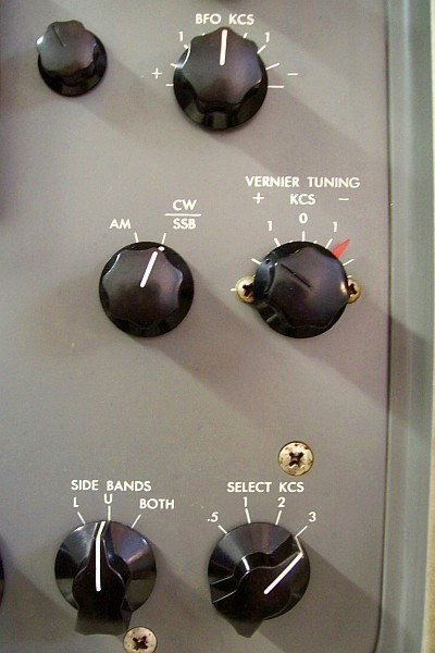 |
Vernier/Sideband accurate adjust: On SSB the VERNIER TUNING control always must point the center of the selected sideband, which is the +/- 1,5 division of the knob dial. This is respectively coordinated with L/U sideband positions.
- BFO KCS knob position for SSB reception (standard operation and options).
- HQ-180: BFO KCS always at center, internal BFO coil adjusted at IF center.
- HQ-180A in SSB position: BFO KCS in any position, internal BFO coil adjusted at IF center.
- HQ-180A in CW position: BFO KCS turned to the +0.5 division, internal BFO coil adjusted at IF center.
- VERNIER TUNING sets location and length (from the IF center) of the "SSB decode area", hence the pitch gradation, that is why precise adjustment of this control is so important.
- SIDE BANDS selects the "IF decode channel" that must match with the center of the VERNIER TUNING location ("+" for "L", and "-" for "U"; in this case) that has the "SSB decode area".
- SELECT KCS defines the area (bandwidth) to be considered from the center point defined by the VERNIER TUNING.
With these settings the SSB signals can (and must) be tuned very easily using the MAIN TUNING control and/or retouching the BAND SPREAD control; it should NEVER be necessary to adjust the VERNIER TUNING control to receive an SSB signal. Always tune an SSB signal via the BAND SPREAD to the corresponding VERNIER TUNING position, as this centers the incoming signal in the selected IF passband (IF sideband). If this configuration cannot be achieved the SSB system very surely is badly adjusted, and this implies difficulty on tuning (narrow heterodyne shifting), off-key audio response on tuning, and also dubious sideband separation to achieve the high selectivity that this system can offer (and all this affects audio response of course).
On AM the VERNIER TUNING control must be located always at center "0" and the SIDE BANDS switch on "BOTH", the function of this control is NOT to be a clarifier (although it has that effect). Signals must always be clarified using MAIN TUNING or/and BAND SPREAD.
And how can be deduced in an imaginary redesign, the vernier tuning could be a fixed capacitive value associated with the SIDE BANDS switch. In "L" with a higher value, in "U" with a lower value, and in BOTH with an intermediate value. When this system is used correctly, the vernier should only be adjusted in 3 locations: at center for AM, and at center of each sideband for SSB. It is not correct to use VERNIER TUNING as a clarifier because it is a location selector in the IF bandpass, not a tuning selector. |
The HC-10 SSB reception method and test page shows design info and test procedures on the Hammarlund SSB system.
|
AM sidebands test
- Tune the AM signal, VERNIER TUNING to "0" with SIDE BANDS to "BOTH" and SELECT KCS to ".5" until maximum
S-Meter deflection is achieved, this should represent that the carrier is in the middle of sidebands.
- Switch to SSB with BFO KCS at center, the result should be zero beat, return to AM.
- When switching SIDE BANDS to "U" and "L", combined with several SELECT KCS positions, the level of modulation
and S-Meter indication should show balanced results, but in this system
this is hard to achieve due the asymmetric IF peaks that produce absence
of a centered flatness.
|
The noise test that
does not test noise
An easy test to check correct working condition of this system: It's
about using the noise floor as if it were a broadband generator, the steps are:
- 1) Select any band from the .54 to 7.85 Mcs range (double conversion).
- 2) Mode to AM, VERNIER TUNING at "0", SIDE BANDS to BOTH, SELECT KCS to 3 (or best 2).
- 3) Rotate VERNIER TUNING from full left and vice versa.
- 4) Noise must be weaker at the ends and stronger at the center.
- 5) Set SIDE BANDS to "L".
- 6) Rotate VERNIER TUNING again from full left and vice versa.
- 7) Noise must be weaker at the left end and up to 2/3 of the right way, and stronger at 1/3 of the left
way (approx).
- 8) Set SIDE BANDS to "U".
- 9) Rotate VERNIER TUNING again from full left and vice versa.
- 10) Noise must be weaker at the right end and up to 2/3 of the left way, and stronger at 1/3 of the right
way (approx).
- 11) Select any band from the 7.85 to 30 Mcs range (triple conversion), and repeat all steps of above.
Bandpass (sidebands) centering test (checking the accuracy of the noise test). In this type of receivers dial calibration is related to pass band and BFO adjustment:
- 1) SIDE BANDS: BOTH, SELECT KCS: .5, BFO: 0, VERNIER TUNING: 0, AM, CAL position (ON). SLOT OFF (+/-5Kc).
- 2) Tune with BAND SPREAD the CAL signal at max S deflection, use RF to locate the needle at '3'.
- 3) Switch to SSB position.
- 4) Zero beat (silence or a very low tone) must being heard if sideband centering (passband-vernier tuning) and BFO are internally well adjusted.
|
Calibrator Check | Dial Accuracy
- Switch to CAL. Voltage to the calibrator circuit is NOT stabilized in this model (DC output is connected to pin 4 of Z1).
- Use a frequency counter capacitively coupled near to pin 2 of the Z1 "integrated
circuit", or inside the tube shield using a loop.
- Try to achieve 100.000 cycles slowly adjusting the ceramic trimmer C50 (*).
(*) When adjusting C50, if the frequency reading cannot achieve 100 Kcs (or suddenly makes a jump),
the ceramic trimmer may be "freezed" or out of range, thus it cannot correct
the CAL frequency. C50 sets the calibrator at the crystal nominal
frequency of 100 Kcs. This is important because if the calibrator oscillates
at e.g. 99.990 cycles an error of 10 cycles is being produced each 100
Kcs, that means 100 cycles to each megacycle, then the error at 30 Mcs
will be 3 Kcs. Also the inability to reach 100 Kcs may be a crystal issue, Hammarlund
says about it: "The frequency of the crystal can be raised by substituting
an external 470 Kohms resistor for the one in the Z1. This is accomplished
by unsoldering lead 7 of Z1 from one side of the trimmer and connecting
the external 470 Kohm resistor across the trimer terminal. This change
will usually make it possible to zero beat a crystal that is too low and
out of the range of adjustment provided by the trimmer".
On a HQ-180 calibrated dial, the local oscillator drift that can occur during the course of a Ham band session should be corrected using MAIN TUNING, not BANDSPREAD. If it is done with BANDSPREAD dial calibration will be lost.
Tuning and receiving SSB on a calibrated dial:
To understand dial calibration, it is necessary to refer to the effects of the settings stated in the manuals for this unusual SSB system: A BFO is used to create a 60 Kc "carrier", that is exact to the low IF design value; and the VERNIER TUNING converter is by default adjusted at center, thus converting an incoming SSB signal to a 60 Kc IF signal which matches the value of the IF... which ALSO matches the BFO value!!! All this does not make sense, it is clear that the incoming SSB signal must be located in a sideband of the IF passband, beating with the BFO; not in the center of the IF passband, colliding with the BFO. Considering all this, muddy audio, distortion, and critical demodulation are the usual consequences, all caused by sideshifts when tuning the input signal with the BFO "carrier". A botched job.
On a calibrated HQ-180 dial (calibrated AM-style as usual via the 100 Kc calibrator: BFO center, VERNIER TUNING center, SIDEBANDS BOTH, and for absolute accuracy SELECT KCS .5/1), when receiving SSB and selecting the center of the sideband via VERNIER TUNING at +/- 1.5 Kc (as I strongly recommend for quality audio and easy tuning), dial frequency "will get wrong" +/- several Kcs depending on the L/U sideband. The combination of BFO at center and VERNIER TUNING selecting the center of a sideband, places the SSB signal into the corresponding IF sideband channel, but we need to extract AF from that sideband. The "BFO" is by design used to insert "a carrier" in the middle of the IF, it is only adjustable in order to match the standard IF value (if it is used for something else operational contradictions will appear). The only solution available is to decode the AF contained in the sideband via MAIN/BANDSPREAD tuning, but this causes the aforementioned frequency shift on an AM-style calibrated dial. If VERNIER TUNING is located at center, frequency reading will be accurate, but as explained above, tuning will be awkward by having random and narrow pitch changes; the gradual pitch shift, which is key in SSB demodulation, will be lost. Therefore, VERNIER TUNING at +/- 1.5 Kc depending on L/U is the correct operating procedure on this SSB system. But when using a calibrated AM-style dial there will be a side effect, there will be some +/- deviation in frequency reading; this is the consequence of changing the location of the signal from the IF center to the corresponding sideband. Therefore, in SSB mode, the dial must be calibrated in that same mode, INCLUDING the offset +/-, that is, zero beat at +/- 1.5 Kc locations depending on Lower/Upper. SSB needs SSB dial calibration when the recommended VERNIER TUNING correction of +/- 1.5 Kcs is applied (this correction is absolutely necessary when quality audio and ease tuning are required). In SSB mode, zero beat calibration is related to actual knob positions, making dial calibration extremely easy.
BAND SPREAD calibration:
This control permits calibrated fine tuning and fine frequency reading in several band spread frequencies that are included in the tuning ranges, but not anyplace throughout the tuning ranges. Due the common issue on tube receivers is lack of accuracy on frequency reading, a calibrator is a must. About that, the main dial is provided with markers below the scales at 4.04, 7.3, 14.425, 21.6, and 29.7 Mcs to be used in Ham Bands, these markers must be located just below the static hairline, after that, the band spread dial can tune amateur bands accurately using the zero beat procedure explained below.
Medium wave (MF broadcast band ranges) and 1.8 Mcs Ham Band dial calibration:
- • The BAND SPREAD knob has no effect on the low end ranges (.54-1.05 & 1.05-2.05), therefore this knob can be left in any position when receiving on these frequencies. In this case dial accuracy must be adjusted internally, and then balanced (checking current setting at different dial positions). As the balance between frequency markers is not perfect, these two ranges will never have dial accuracy. This significant dial inaccuracy would have been resolved by making the hairline on the main dial adjustable.
Accurate dial calibration for 3.5 - 7 - 14 - 21 - 28 Mcs Ham Bands:
- 1) MAIN TUNING: select the Ham Band high frequency marker of the desired band under the static hairline.
- 2) SELECT KCS: .5, SIDE BANDS: BOTH, BFO: 0, VERNIER TUNING: 0, switch to SSB (model A) CW/SSB (non A), CAL (ON).
- 3) Adjust hairline at CENTER of the BAND SPREAD dial using the small knob at right.
- 4) BAND SPREAD: select a multiple of 100 Kcs in the desired frequency group and match it to the BANDSPREAD hairline.
- 5) Tune zero beat with MAIN TUNING (this usually unmatches the hairline from the high frequency marker, this is normal).
- 6) CAL OFF (RECEIVE position) and set the rest of controls as desired.
- • After that, you can fine tune using the BAND SPREAD knob and dial; subsequent 100 Kc divisions on dial may be checked CALIBRATOR ON and a new zero beat should be heard at the next 100 Kc mark underneath the hairline; otherwise adjust the hairline to the 100 Kc dial mark. This procedure is more useful than others since it covers displacements that may will go beyond the mechanical range of the adjustable hairline.
Non-bandspreaded frequencies calibration
Hammarlund says the 0 to 100 arbitrary scale may be used for accurate dialing, counting intervals relative to frequencies and logging of values. An example of a procedure based on this, applied to the 15.35 - 30 Mcs range, may be: BAND SPREAD to 29.650, MAIN TUNING located pointing a frequency multiple of 100 Kc that is within the desired range, and after BAND SPREAD is retouched to obtain zero beat. Main dial informs exact tuned frequency, and when BAND SPREAD is operated, its dial informs how many kilocicles to be added (when displacement is at left) / substracted (when displacement is at right) to the main dial frequency mark. When changing to another frequency BAND SPREAD must be "zeroed" repeating the procedure.
It works, but reading the frequency directly on the main dial is better, for this I use the following procedure:
- 1) BAND SPREAD to end scale (100).
- 2) MAIN TUNING adjusted to a frecuency multiple of 100Kc.
- 3) CAL ON.
- 4) Adjust BAND SPREAD to zero beat.
- 5) CAL OFF.
- 6) Now MAIN TUNING can tune accurately frequencies around the adjusted frequency.
But it can only be used in ranges where the capacity of the bandspread capacitor is effective, and also has a requiremet: As BAND SPREAD can only be adjusted to the left, MAIN TUNING must move towards the zero beat from a lower capacity location (to the right). When aligning the receiver this must be taken into account, accuracy errors throughout the MAIN TUNING range need to be located on the left of the exact frequency, thus allowing combined use with BAND SPREAD.
All of these bizarre procedures for the non-bandspreaded frequencies could have been avoided simply by making the MAIN TUNING dial hairline adjustable. That a receiver in this category does not have calibrated tuning throughout the tuning range is a drawback, also is a drawback that the SP-600 does not include a calibrator. It seems Hammarlund found it difficult to design "finished" receivers.
|
SLOT FREQ | Slot Depth (control behind panel) test
- Set mode switch to AM, VERNIER TUNING to "0", BFO KCS at center, AVC to FAST, and NOISE LIMITER to OFF.
- Set SIDE BANDS switch to BOTH.
- Set SELECT KCS to ".5".
- Set TUNING RANGE MCS to about 1.9 or 3.6 or 7.1 or 14.1 Mcs, this is important only for the amount of
harmonic output that affects the S-Meter deflection.
- Set function switch to CAL and tune CAL signal at maximun S-Meter indication.
- Adjust RF gain control for a S-Meter reading of 5, retune CAL signal.
- Set the mode switch to SSB: The result must be zero beat; return to AM.
- Set SLOT FREQ for a minimum reading on the S-Meter.
- Rotate the Slot Depth adjust (control located behind front panel, accessible by opening the upper gate) in order to
decrease the minimum reading, retouch SLOT FREQ checking this.
- If SLOT FREQ is located at "0" when the S-meter indicates the minimum reading, these controls are OK.
- If SLOT FREQ is not located at "0", set this control to "0", and then adjust L3 in order to achieve
a minimum reading on the S-Meter.
|
Checkpoints
Checking what we have in front is the first step, this should always be done before
trying to adjust something. Believing that something is unadjusted, or
believing that the real values of adjustment are those of design is the
perfect method to make mistakes. It must be remebered that SIDE BANDS at
"L" is in fact at "U" in the circuit, sidebands are marked inverted on the
panel due the 1st mixer phase reversal effect. Signal sources for testing can be the calibrator
and/or a signal generator, both used to achieve maximum S-Meter deflection.
- Frequency of oscillation of the 1st mixer (LO) can be tested with a frequency counter capacitively
coupled(*) to pin 1 of V2 (grid). (*) Not by contact; clamping the wire insulation with an alligator clip, or bringing a wire closer from the FC as "antenna".
- Tuned frequency of the 3,035 Mcs Xtal filter (it works on 7.85 to 30 Mcs range only) can be tested
injecting a signal capacitively coupled to the pin 5 of V2 (plate).
Set VERNIER at left and after at right, recheck signal generator frequency,
S-Meter movement will be less left/right and maximum when VERNIER is at
center or at maximun resonance (~3,025,000 cs in this unit, not standard, read below).
- Frequency of oscillation of the of the 1st Converter (XLO) can be tested with a FC
capacitively coupled to pin 1 of V3: ~2,580,000 cs (frequency of crystal).
- Tuned frequency of the 455 Kc IF chain can be tested selecting any band among the .54 to 7.85 Mcs range, and then injecting a signal capacitively coupled to pin 1 of V18 (V17 in model A, the 455Kc gate, this stage works only in the .54 to 7.85 Mcs range), AM, VERNIER
at center, SELECT KCS at 0.5, SIDE BANDS to "BOTH". Set VERNIER at left
and after at right, recheck signal generator frequency, S-Meter movement
will be less left/right and maximum when VERNIER is at center or at maximun
resonance (~445,200 cs in this unit, not standard, read below).
- Tuned frequency of the 60 Kc IF chain can be tested injecting a signal to the junction of C28/T5 (or pin 7 of V5)
and chassis, AM, VERNIER at center, SELECT KCS at 0.5, SIDE BANDS to BOTH. S-Meter will show maximum resonance, then read frequency on the signal generator dial or/and a frequency counter connected to it (~60,300 cs in this unit).
- A better alignment indication will be obtained by placing a VTVM at the 'diode load' checkpoint, which is the junction of L8 and C44.
- Frequency of oscillation at center of the BFO can be tested BFO ON with a FC capacitively
coupled to the stator of the variable capacitor C129 (~60,300 cs in this unit). Model A: this capacitor is out of circuit on SSB position, it only works on CW position.
- Frequency of oscillation at center of the 2nd Converter (LO, VERNIER TUNING) can be tested with a FC capacitively coupled to the lateral lateral lug of the variable capacitor
C156 (~384,900 cs in this unit).
- AGC level: AVC terminal on the rear. Voltmeter, negative lead to AVC terminal, positive lead to chassis (GND).
|
Intermediate Frequencies
in this unit (due it uses a 3025 Kcs Xtal filter, not 3035 Kcs)
Antenna input RF LOW: .54 to 7.85 Mcs range only (contains one conversion, continues on IF STAGES).
- 1st mixer output: ~445 Kcs (NOT 455 as per specs), followed by a 445 Kcs IF amplifier gate. Frequency
Received by the antenna - Frequency of the Local Oscillator (FR + 445 Kcs).
This mixer reverses sideband positioning.
Antenna input RF HIGH: 7.85 to 30 Mcs range only (contains two conversions, continues
on IF STAGES).
- 1st mixer output: ~3,025 Kcs (NOT 3,035 as per specs), followed by a 3,025 Kcs Xtal phasing fixed
filter and the 1st converter. This is the Frequency Received by the
antenna - Frequency of the Local Oscillator (F.R. + 3,025 Kcs).
This mixer reverses sideband positioning.
- 1st converter output: ~445 Kcs IF (NOT 455 as per specs) that is = ~3,025 Kcs (1st mixer IF input)
- ~2,580 Kcs (Local Xtal Oscillator).
IF STAGES: 445 Kc & 60 Kc (contains one conversion).
- ~445 Kcs IF amplifier (NOT 455 as per specs) followed by a +/- 5 Kcs SLOT filter adjustable on panel.
- 2nd converter: ~60 Kcs output = ~445 Kcs (IF stage output) - ~385 Kcs VERNIER
TUNING frequency at "0" (NOT 395 Kcs as per specs).
The difference of 10 Kc in the medium IF is produced by the first mixer: Xtal is 3,025,
not 3,035. The Xtal installed is original, not a mod made by someone. It
is very usual on multi-conversion receivers to accommodate the last IF to
previous mismatches (variations are transferred to the rest of circuit
adjustments in order to obtain best functional operation). Never
must be believed that the stated IF in the manual or schematic
is the actual frequency, but of course, this difference is excessive.
Usually mixer variations to accommodate dial accuracy are very common,
but an exact difference of 10 Kc is very suspicious: A temporal mod
in design or an Xtal error deemed irrelevant by the employee who made the adjustment?
In view of all of the above, the nominal IF of this particular unit does not match with
the standard IF stated in the manual, but in practice the result is equivalent.
This HQ-180 works excellent on all bands, due this, the stated change from the
nominal IF value is irrelevant. For a perfect adjustment of the sideband - bandwidth system, a good understanding of how this system works is mandatory, but Hammarlund doesn't help on this; sometimes on reading manuals gives the feeling that not even Hammarlund knew exactly how the system worked.
This unit features components dated 1960 suggesting that it was assembled in 1961, or at the latest in 1962, therefore it was one of the last non-A HQ-180s produced. The HQ-180 Model A was released in 1963, and just 10 years later, Hammarlund disappeared. This curious 10 Kc issue with the crystal underscores what is explained for the HQ-180A manuals of 1963 and 1970: Errors and inaccuracies, questionable technical solutions such as keeping the receiver plugged in 24/7 to achieve frequency stability, and the fact that they apparently didn't even understand how to adjust something they had built themselves. IMO, the sale of Hammarlund to EAC reflected this and hastened the company's demise.
HQ-180 / SP-600 Comparison
Comparison with SP-600 becomes inevitable, SP-600 and HQ-180 shares similar design in several circuits but HQ-180 has updated design. SP-600 is a dual conversion receiver, HQ-180 is a triple conversion receiver and has more options on panel... BTW: when comparing schematics, an amazing thing is that SP-600 lacks crystal calibrator as its schematic shows. This is an important absence, a tube receiver always needs a calibrator to adjust accurately its dial ranges. On this regard, I would recommend to those who own an SP-600 (and do not own this receiver for decorative purposes in a shack), to evaluate the option of using the crystal module (currently useless) into a double frequency Xtal calibrator (100 Kc and 1 Mc, or more in this case). This could be done by separating the function of that module as an optional XLO from the circuit and then connecting its output to the antenna socket via a small capacitor... but unfortunately this would be for testing purposes only (see next).
As a trade off, SP-600 has better mechanical dial operation, i.e. a single tuning knob operates coarse and fine dials allowing fine tuning on all ranges; but perhaps it would have been better if the dial above the tuning knob would have been the frequency dial (main, at left), not the fine reading dial (right), since this dial is not what it seems (a fine frequency dial or a band spread dial), it is an arbitrary scale from 0 to 100 related to the outer arbitrary scale numbered in sectors of the main dial.
SP-600 does not have a system to read frequencies accurately, it has a procedure to log dial positions accurately, and the logged info correspond to the real frequencies. SP-600 shows coarse frequency indication along with mechanical position areas on the main dial, and fine mechanical positions on the vernier dial; a combined "code" is created with those two readings, and then this info must be logged as if it were a frequency annotation. Since the annotation will be correct as long as the SP-600 does not drift, a calibrator is also needed to check the annotation. SP-600 needs a calibrator of course, but the mechanical design makes it difficult to "float" the pointer on the main dial of the SP-600. Maybe for these reasons SP-600 does not have calibrator. By applying this system, Hammarlund attempts to "leapfrog" dial frequency accuracy, turning "receiving at the frequency of..." into "receiving at the location of...". Nowadays, probably the best method is to tune using the coarse (main, left) frequency dial first, and then refer to the fine dial (arbitrary scale, right) for an exact vernier location indicating "frequency".
Summarizing and in view of all the facts: I suspect that HQ-180 replaces SP-600 with advantage.
|


