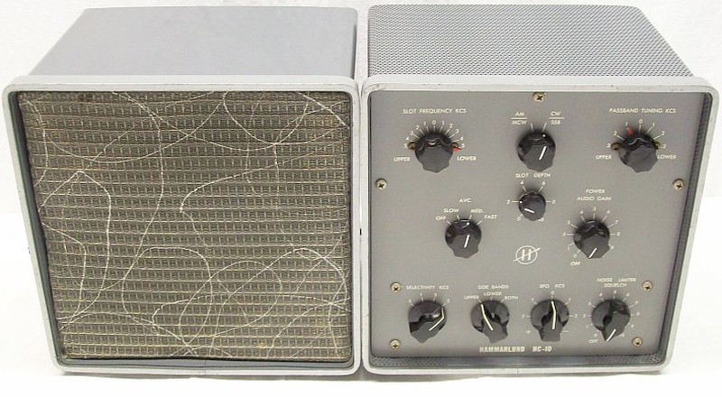
An IF converter is an electronic circuit that, by means of using the heterodyne principle, converts a receiver's IF into another IF to be processed in additional circuits that permits new operational functions (do not confuse with an RF converter). If an IF converter is connected to a receiver, all receiver circuits following the IF input of the converter will no longer be used, since the converter will replace them all.
450 to 500 Kc by adjustable coil slug on the rear to 60 Kc IF. In this particular model the covered IF range goes from 450 to 530 Kc. Thus it covers from the popular IF of 455 Kcs (Hammarlund, Collins, etc.) to the less popular IF of 525 Kcs (some Telefunken models). This converter must be connected to an stable IF output because the system used for selecting sidebands requires exact input. Never must be believed that the nominal IF on an schematic is the receiver's adjusted IF factual/operational value.
Easy to use converter, but may be a puzzle to understand the system used for selecting sidebands and signal selectivity. Adding this converter to a regular receiver greatly improves reception and also adds new options that the receiver may not have.
Smart approachment found on eBay: pilot light added to front panel along with the headphone jack removed from rear panel. This requires holes in front panel, it is not advisable to make mods to front panel, but the phones jack and a pilot light should have been included there from factory.
Unfortunately, HC-10 does not have a pilot light, it turns out that the receiver to which it is connected is used as "pilot light" using the 'Controlled AC' outlet.
Intended to make the HC-10 compatible with various mains voltages and to give frequency accuracy at the input and its marking on the PASSBAND TUNING dial.
Added: - Fine Passband Tuning adjust
in order to get accurate passband indication on panel.
- More AC power line options.
Modified: - Noise Limiter.
- Power supply.
Deleted: - Controlled AC output, now it is mains input.
Input Signal, voltage range.
5 mV to 2 V.
Excellent range.
Input impedance & Rx connection.
Medium. Direct from 50 ohms (R-390A) to interstage transformer impedances (HQ-160). Other impedances
will require special adapter.
450 to 500 Kc (input signal)
LO (PASSBAND TUNING 390 to 440 Kcs, works as fine input frequency adjust).
Output: Three 60 Kc IF stages
(2 amplifier + 1 output driver).
Phase reversal.
No reversion. This converter doesn't reverse sidebands due LO frequency is below the input signal. Upper and Lower marks are labeled real on the panel, but THIS MARKING MAY BE REVERSED regarding to the tuned signal of the receiver to which it is connected; an "X" receiver may change sideband positioning due to its own conversion process: "LOWER" will process USB signals and "UPPER" will process LSB signals.
IMPORTANT! The SIDEBANDS LOWER/UPPER indications may be wrong (inverted) depending on the characteristics of the receiver to which the HC-10 is connected. These indications will only be correct when the receiver to which the HC-10 is connected does not invert sidebands or inverts them an even number of times. With an odd total number of inversions LOWER is now UPPER, and UPPER is now LOWER.
e.g. Connecting the HC-10 to the Hammarlund HQ-160: 1) HC-10 does not reverse sidebands (low-side mixer) 2) HQ-160 reverse ONCE below 10 Mcs and TWICE above 10 Mcs (phase inversion zero above 10 Mcs). Therefore the odd inversion is up to 10 Mcs. In this range to receive LSB the SIDEBANDS switch must be set to UPPER, and to receive USB to LOWER.
Receiver → Converter connection. Using the calibrator / unmodulated signal processed at receiver "X" (must have S-Meter).
Manual instructs about using an AM tuned signal and then set zero beat against its carrier; the AM signal must be very well centered. Not so accurate, but useful when there is no S-Meter or Signal Generator.
After some warm-up time:
"X" receiver: - AM mode.
- Select narrowest selectivity.
- Adjust moderate RF gain.
- Calibrator ON.
- Tune CAL to MAX S-Meter.
HC-10: - CW/SSB position (BFO ON).
- PASSBAND TUNING to "0".
- BFO KCS to "0" (*). - SELECTIVITY KCS to ".5"
- SIDEBANDS to "BOTH".
- Rotate the coarse PASSBAND ADJUSTMENT slug (rear of the converter) using an exact hexagonal size tool until zero beat is achieved. This adjust must be accurate. Warning! Hammarlund coil slugs are fragile and coil forms tend to squeeze (**).
"X" receiver: - Make sure Cal signal is
still tuned at maximum S-Meter deviation (center of receiver's IF).
- Calibrator OFF.
- Select wide selectivity.
- Increase RF gain.
- Audio gain to MIN.
HC-10: - CW/SSB operation: PASSBAND
TUNING to '1.5' UPPER or LOWER depending on receiver's phase reversal, SIDE BANDS to UPPER
or LOWER depending on PASSBAND TUNING indication.
- AM/MCW operation: PASSBAND TUNING to "0", SIDE BANDS to BOTH.
Maximum deviation of the "X" receiver S-Meter
assures receiver → converter alignment (both at minimun selectivity).
Making a precise adjust is very important due the peculiar system used, if receiver & converter IF centers do not
match accurately, both performance and sideband separation will be degraded.
(*)The BFO at '0' should be oscillating at 60 Kc. For SSB reception this control MUST NOT BE TOUCHED, it MUST always be at '0', if it needs to be touched something is wrong or the HC-10 is not being adjusted OK, and then audio problems will start. It should only be adjusted away from '0' for CW reception.
(**) Never force the slugs on these coils. When new they tend to go hard and get stuck, but when touched up too many times they tend to loosen up and have slack, so getting an exact zero beat can be difficult.
• For proper operation the zero beat should always be located at '0' on PASSBAND TUNING and also at 'O' on BFO. For CW reception the BFO should be set slightly off '0' to give the beat note. For SSB reception the BFO should always be at '0', what should be offset is PASSBAND TUNING that must be set at '1.5' UPPER or LOWER depending on whether the signal is USB or LSB, but this can be reversed as explained in 'Phase reversal' above.
AM detection by...
Diode
Connected to 60 Kc IF output driver
FM detection by...
Diode, resonance slope, sideband skirt.
Processed by the 60 Kc IF
stage. SELECTIVITY KCS always at '3'.
FM operation
AM mode
PASSBAND TUNING at center
SELECT KCS on "3"
SIDE BANDS on "L" or U"
(*)
(*) Audio quality depends
of the less vertical skirt of the response curve (the FM detection by signal
slope processes very well human voice when resonance slope is ±60
degrees).
SSB/CW detection by...
Plate detector, mixer type
(double triode product detector).
BFO and signal are injected separately to grids.
AVC (AGC) stages controlled
2, fast and delayed combined. 455 Kc mixer + first 60 Kc IF.
AGC circuit is slightly different compared to HQ-170/180 circuits.
AVC (AGC) switch
OFF, SLOW, MED, FAST positions.
FAST for AM/CW reception.
AVC (AGC) on SSB/CW
YES
SLOW, MED/FAST positions.
AVC (AGC) IN/OUT
YES, rear panel.
IN for AGC muting. OUT for AGC linking.
S-Meter
NO
YES in model SPC-10.
Product Detector
Double triode design type
Excellent performance
BFO KCS
Range ± 1.9 Kc from
center "0".
Works on CW/SSB position.
+ range: BFO frecuency
INcreases.
- range: BFO
frequency DEcreases.
BFO receiving SSB
Positioned at center
mark. Hammarlund's system requires this control be located always
on "0" for SSB, this means carrier insertion at center of the AM bandpass.
"AM-carrier" insertion in the IF 60 KC chain.
BFO receiving CW
CW signal must be tuned
at zero beat, then adjust desired tone.
This control ONLY must be
rotated out of "0" when receiving CW.
Function/Mode switch
AM/MCW - CW/SSB
SIDE BANDS switch
L (lower) - U (upper) - BOTH
On BOTH, the 1 - 2 - 3 bandwidths of SELEC KCS are being doubled.
SELEC KCS switch
.5 - 1 - 2 - 3 Kcs
.5 - 1 Kcs (CW - BOTH)
2 - 3 Kcs (SSB - L/U or AM - BOTH)
PASSBAND TUNING is the Local
Oscillator of the converter, selects the exact output frequency injected
to the 60 Kc IF chain.
Moves the incoming signal
across the passband. Adjustable ± 3 Kcs IF passband tuning range.
Centered at "0" is for AM/CW. In order to get accurate SSB tuning this
control must be turned to '+1.5' for lower sideband (SIDE BANDS at "L" or
"BOTH") and '-1.5' for upper sideband (SIDE BANDS at "U" or "BOTH").
In the HQ-170 and 180 receivers
this control is labeled VERNIER TUNING, this creates a misunderstanding
to user; it is believed to be a fine input signal tuning when
it is a frequency conversion fine tuning.
Permits centered adjust of the incoming SSB signal when this control is rotated to the "LOWER" or "UPPER" side. Must be located at center for AM/CW, and '-1.5' or '+1.5' for SSB. Correct setting of this control (besides static adjust of the BFO at center) is VERY important for the performance on SSB. When it is located at '+1.5' or '-1.5' the incoming signal is tuned at the sideband center. This control can be used to make fine adjust as the manual says, but it should not be used in this manner, this SSB system requires accurate and reliable adjust.
The HC-10 manual says that this control should be used as the fine adjustment, so it will rarely stay centered at "0", and so the dial will never indicate the exact position of the sideband relative to "0". To adjust reception on a sideband this control should be set to '+1.5' or '-1.5', and that position is a fixed adjustment, not a variable one. If this control is used to adjust reception, the sideband demodulation will never be correct. Because of this, an air trimmer capacitor has been added in parallel to the passband tuning capacitor, this allows the PASSBAND TUNING at "0" to accurately match the center of the incoming IF and allows the dial indication to be reliable for adjusting sideband reception.
SLOT FREQUENCY KCS
IF passband null slot location
Range ± 5 kc IF center. Adjustment: Rotate the SLOT FREQUENCY
control to "0" and adjust SLOT FREQUENCY KCS
slug through the hole located at upper left side of cabinet for minimal sound; then rotate
SLOT DEPTH as necessary to further reduce sound. This adjust is not critical.
SLOT DEPTH
Rejection level adjust
Useful for CW, it should
always be set to maximum. Usually max-att (rejection depth) is 20% advanced.
NOISE LIMITER - SQUELCH
SQUELCH? This circuit does
not work properly as squelch because it is not an squelch circuit.
OFF and adjustable clipping
effect, full wave.
Useful for random noise
pulses, useless for extremely short duration pulses and hiss-like noise
picked up by the antenna, works on all modes of reception. HQ-170 & 180
have identical circuit, but the HC-10's NL produces distorted audio
just connected because the AGC line is incomplete.
Noise Limiter circuit has been slightly modified for best receiver → converter adaptation without AGC linking (the easiest use).
A negative bias source has been added to compensate for the lack of bias voltage (provided by the previous stages in a complete receiver) to the low-IF circuit to the Noise Limiter, this lack of voltage causes distortion just by connecting it.
AUDIO GAIN
Adjusts audio level.
Hammarlund auto-response circuit (a simplified Williamson-type feedback circuit).
PHONE output
YES, 3.2 ohm.
Uses same 3.2 ohm transformer winding output for speaker.
YES, but it has been changed to another hole on the right (the original power cord hole). The current location makes it easier to plug and unplug phones.
Line voltage
115 VAC.
No export model nor A model exists.
New power supply transformer. IN: 110, 125, 230 VAC options.
OUT: 270-0-270 / 6.3 / 6.3 VAC. The new transformer's single 6.3V filament voltage forces the original 5Y3 tube rectifier (5 volts) to be replaced with the 6AX5 tube rectifier (6.3 VFil).
Controlled AC output
115 VAC.
Due to the limitations of the potentiometer switch, this socket can only be used to connect a limited current load, five tube radios or similar.
This socket is now used as the mains voltage input.
.
Cabinet removal
7 screws must be removed.
- 3 upper phillips screws
on front panel.
- 4 hexagonals, underside the cabinet.
- The 4 lower phillips screws
on front panel must remain tight.
Speaker
Model S-100, to rear outlet.
Speaker cabinet has same
dimensions as HC-10 cabinet.
Design values
Important key text extracted from the manual:
"To obtain the full advantage of the HC-10 converter, its initial adjustment must be made to the exact intermediate frequency of the receiver with which it will be used."
Intermediate Frequencies:
INPUT: 450 to 500 Kc IF from the "X" receiver + adjustable SLOT DEPTH circuit followed by a 60 Kc IF converter.
60 Kcs IF output = 450/500 Kcs (receiver's IF stage output) less 390/440 Kcs (LO slug, PASSBAND TUNING at "0").
SIDE BANDS, centers / SELECT KC, flatness
KC
Upper position
Lower position
BOTH position
.5
60.000
±60.000
±60.000
1
60.500
59.500
60.000
2
61.000
59.000
60.000
3
61.500
58.500
60.000
Idealized (theoretical, hard to find in a real unit) peak resonances
on respective positions of selectivity. The resonance ".5" at "U" (equivalent to ".5" at "BOTH" but "U" has less bandwidth) is the correct BFO frequency on SSB.
In practice, the resonances above do not match those found in a real circuit due imperfections in centered flatness and symmetrical response.
BOTH decreases plate load resistance allowing wide bandpass.
Choosing BOTH, the
offset value (500 Cs) is doubled (except on ".5" KC position). Current
off center shift is less than 1500 cs due the system provides overlapping
at center on BOTH. When other bandwidth/sideband combination is selected
the peak response varies due the action of fixed coupling/tuning capacitors
and loading resistors.
Hammarlund system always adjusts on the Upper sideband. The manual says UPPER position must be selected when the IF stage is being adjusted at ".5" position in order to get the maximum accurate adjust, but resonance at .5 is almost the same on LOWER and BOTH. The other KCS SELECTIVITY positions reduce Q and broaden the frequency response. Performance beyond the .5 KCS depends on exact values of capacitors and resistors involved in the selected circuit.
This system is based on switching different values of capacitors and resistorsthat changes sideband bandwidth in the IF chain. The LOWER position selects a circuit with no previous adjust, its adjust depends on component values, due this this position may have less performance than the UPPER position.
BFO must be adjusted at center '0' and this position must generate a 60 KC beating signal, the BFO control should only must be adjusted off-center in order to adjust CW tone when receiving CW.
Checking the correct operating status of the system:
Tune a SSB signal on BOTH, BFO KCS at center, for perfect tuning rotate PASSBAND TUNING to '+1.5' or '-1.5' depending on Lower or Upper sideband. Change SIDE BANDS to UPPER or LOWER when the correct sideband has been checked.
Set selectivity switch at the narrowest bandwidth position (.5) and change "L" to "U" and vice-versa: Tuned signal at .5 may be weaker and sounding obscure but should not disappear, copiable and understandable depending on its strength.
Set selectivity switch to 1, 2, and 3 successively selecting sidebands: A LSB signal on "L" must be received OK, and on "U" must be weaker or almost disappear depending on its strength; in like manner, a USB signal on "U" must be received OK, and on "L" must be weaker or almost disappear depending on its strength.
There should be no need to retune even when changing switch positions, but since the HC-10 is connected to an "X" receiver, some discrepancy in the point of maximum signal strength could be allowed.
Trying to show a simplified view: Clearing up misunderstandings on this SSB system.
• The BFO replaces the AM carrier, which is always centered in the IF and between the two sidebands. But the role of PASSBAND TUNING is not defined in the manual, it says to set it to "0" and adjusting the other controls as necessary. This doesn't make sense and is easily provable: As the BFO control must remain always at "0", if the PASSBAND TUNING control is also at "0", there will not be enough frequency separation when the "X" receiver tunes a SSB signal; BFO and signal will collide at "0"!
• Thus the incoming SSB signal must move and be processed in the corresponding sideband channel, that's why PASSBAND TUNING must also be adjusted at one side, not at center, therefore an exact match of IF frequencies (receiver/converter) is mandatory, so the PASSBAND TUNING dial reading should be accurate. To reach this:
a) The PASSBAND TUNING control must be adjusted to prepare the sideband receiving channel.
b) The incoming sideband must be selected in the IF chain (L-U).
c) Then the SSB signal from receiver "X" can be processed at a selected selectivity (3-2-1-.5).
• The manual does not mention anything about it; it mistakenly refers that the PASSBAND TUNING control is a fine frequency adjustment when in fact is a UPPER ↔ BOTH (center) ↔ LOWER operating frequency area selector(tuning concept vs location concept), an exact adjust on its dial is needed.
• When receiving SSB, the PASSBAND TUNING control NEVER must remain at center; and when receiving AM/CW the PASSBAND TUNING control ALWAYS must remain at center. This control is NOT a clarifier although it may be used as a clarifier, a lot of HQ-170/180 receivers are badly adjusted due manuals do not explain in detail the particular mode of operation of this system, or/and, give counterproductive info.
• The way to check the receiver/HC-10 frequency centering is:
1) Activate CAL on receiver 'X', and with its BFO at '0' set zero beat.
2) Receiver 'X' with BFO OFF and audio gain at minimum. HC-10 BFO ON (CW/SSB), and with PASSBAND TUNING at '0' and BFO at '0' the zero beat should now be heard in the HC-10 speaker. If not, adjust PASSBAND TUNING until it reaches zero beat. When reached, this would be the correct '0' position for PASSBAND TUNING, but since that zero beat does not coincide with the '0' mark on the PASSBAND TUNING dial, this must be corrected.
3) Set the PASSBAND TUNING to '0' and adjust the PASSBAND ADJUSTMENT slug on the back until zero beat is reached. If this slug has a tendency to jam (very usual), this operation is imprecise and critical: do not force that slug!!! (see the overhaul page at bottom). This is why fine passband adjustment has been installed on this unit.
4) The manual says that PASSBAND TUNING is the fine adjustment, but this is not adequate because this dial will rarely point to zero, and this dial MUST show the center '0' corresponding to the center of the IF in order to operate correctly with this system, i.e. to adjust the fixed positions (+1.5 ↔ 0 ↔ -1.5 with selectivity at 3) that make the HC-10 work properly.
Operation:
• When receiving AM or CW PASSBAND TUNING must be set at '0'.
• When receiving SSB PASSBAND TUNING must be set at '+1.5' or '-1.5' (selecting the center of the sideband channel when SELECTIVITY KCS is at '3').
• When receiving SSB, the BFO must ALWAYS be set to '0', this must result in a 60 Kc signal.
• BFO must be set '+0.5' or '-0.5' when receiving CW.
• These positions are NOT randomly adjustable, the only "adjustment" is the MAIN TUNING of the receiver, and MAIN TUNING should point to the center of the UPPER, BOTH, or LOWER 'channels'. If they need to be adjustable, HC-10 is badly adjusted, same for receiver, or the receiver → converter linking is not OK.
• When a 455 Kc signal enters the converter
a) PASSBAND ADJUSTMENT (the Local Oscillator of the converter) must operate at 395 Kc.
b) SIDE BANDS on BOTH must operate centered at 60 Kc.
c) SELECTIVITY KCS with SIDEBANDS on BOTH must select 3, 2, 1, .5 Kc bandwidths.
d) SIDE BANDS on UPPER or LOWER must select the sideband channel, with SELECTIVITY KCS at '3' it is centered at 1.5 Kc, thus the sideband channels at '3' are 61.5 Kc and 58.5 Kc.
e) If all the above is true HC-10 will work EXCELLENT.
⇒ KEY INFO: This system works with an UPPER ↔ BOTH (center) ↔ LOWER "template" which is not adjustable in terms of locations, it is only adjustable in terms of width, it is the adjustment of the devices that must adapt to locations.
⇒ The manuals give contradictory or inaccurate information about the system, due this it seems that not even Hammarlund understood it (although it may seem nonsensical and incredible to say).
Tube List and associated functions
Function(s)
Tube(s), 10 total
Comments
A-mod
Converter mixer
6BE6 tube (V1)
Fast AGC
PASSBAND TUNING
An air trimmer was added in parallel to the LO trimmer capacitor for fine tuning. This HC-10 has coarse adjustment (slug) and fine adjustment (trimmer).
IF Amplifier 60 Kcs
6BA6 tube (V2)
Fast AGC
SIDE BANDS selection
SELEC KCS selection
IF Amplifier 60 Kcs
6BA6 tube (V3)
SIDE BANDS selection
SELEC KCS selection
IF Output driver-amplifier 60 Kcs
1/3 6BV8 tube (V4A)
SIDE BANDS selection
SELEC KCS selection
Delayed AGC
1/3 6BV8 tube (V4B)
Diode RF rectifier
Detector
1/3 6BV8 tube (V4C)
AM diode detector
Product Detector
12AU7 tube (V5)
CW/SSB mixer, plate detector.
BFO
6C4 tube (V10)
60 Kc oscillator (CW/SSB)
Noise Limiter
6AL5 tube (V7)
Adjustable peak clipping (series type)
Audio distortion due to lack of AGC linkage when NL is activated (counterclockwise ON) has been corrected by adding an adjustable negative bias source.
AGC clamp
2/3 6AV6 tube (V8A)
2 diodes in parallel
Audio Amplifier
1/3 6AV6 tube (V8B)
Triode audio preamplifier
Audio Power Output
6AQ5 tube (V9)
Pentode audio power amplifier
AC Rectifier
5Y3 tube (V6)
AC full wave rectifier
Change: 6AX5 tube.
Contents
Concluding overview
HC-10 is the 'little brother' of the 19-inch rack mount IF converter model SPC-10. Its circuit is the same as the low-IF section of models HQ-170 and HQ-180. Frank Lester from Hammalund defined the HC-10 as a "box of tricks". Very good performance and adaptability, but it looks like a test model, it is small for the amount of circuitry it has, therefore, the placement of components is highly conditioned by the reduced dimensions of the chassis. The HC-10's 'big brother', the SPC-10, has S-Meter, some added circuitry, more size, and made to be mounted into a 19-inch rack (perhaps to be companion of an R-390 or a SP-600). However, there are not many circuit differences between HC-10 and SPC-10, so the performance of both devices should be very similar. Basically the HC-10 is a simplified version of the SPC-10, so HC-10 could be referred to as 'the prototype version' of SPC-10.
HC-10 does not have S-Meter. S-Meter is essential in communications, since in addition to indicating the signal level, it shows the operational adjustment of the system. When the HC-10 is connected to a receiver, the only S-Meter that works is the one in the receiver, but that S-Meter does not show the operation at the HC-10. It is extremely important that the HC-10's input be adjusted with absolute precision to the REAL intermediate frequency of the receiver, otherwise the entire sideband system is affected, and the popular Hammarlund issues with SSB-audio will begin. The main problem when using the HC-10 is that the operator is "blind" to its actual operation due the lack of S-Meter (the lack of a pilot light also contributes to this), the only way to evaluate the adjustment in reception is "by ear", and the only way to work "by ear" efficiently is to have a HC-10 previously adjusted with absolute precision, therefore and consequently the receiver output center frequency must be exactly the same as the HC-10 input center frequency. That is why fine tuning has been incorporated into this unit to achieve precise input tuning, thus allowing accurate marking on the PASSBAND TUNING dial.When receiver → HC-10 adjustment is absolutely accurate, this converter works excellent, just as it did when connected to the HQ-160. It is also very important to take into account that the SIDEBANDS indication LOWER/UPPER may be wrong (inverted). See 'phase reversal' in the table above.
A properly adjusted and connected HC-10 will greatly increase the selectivity and operability of an "X" receiver, especially if it is modest; but there is an important feature that is often forgotten: Bear in mind that for a perfect receiver → converter adaptation, converter AGC voltage should supply receiver AGC line (AGC linkage); but incorrectly, converters are connected without AGC linkage to receivers, this causes some of the expected benefits to be lost. Precisely, just activating the HC-10's Noise Limiter, audio is distorted due the AGC linkage -that automatically exists in models HQ-170/180- is now missing. To avoid this issue, the AGC source voltage of the associated receiver (AGC detector) should be disabled, and its AGC line should be connected subordinated to the HC-10 AGC line (as in models HQ-170/180). This is not always easy, the associated receiver should have, besides the usual AGC OFF option (AGC to ground), an 'AGC input' option; this is, an AGC line released from AGC source voltage.
An HC-10 can be connected to an R-390A very easily giving very good results if the above precautions are taken into account, it only needs a BNC to RCA cable and an accurate adjust to the R-390A's IF output, but in fact the HC-10 is designed to be connected to the middle-class of tube receivers (without "specialties", commercially-made / homebrewed) of the postwar era. When it is connected to high-end tube receivers that have a powerful BFO, long AGC chain, and selectivity (with those circuits working properly), you won't notice much difference. High-end tube receivers can receive SSB/AGC-ON very well without a product detector circuit, only RF GAIN needs to be adjusted, which BTW, will also need to be adjusted with the HC-10 and other converters; e.g. the classic syllabic "bumps" will not be removed without acting on RF GAIN due lack of AGC linkage.