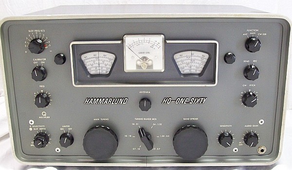
| Hammarlund
HQ-160 (+E) Tech-Spec Page |
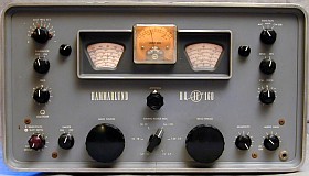 1st ed., old-style painted letters. 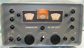 2nd ed., modern-style painted letters. 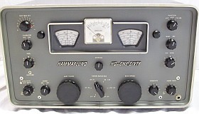 3rd ed., molded plastic cursive letters. |
| Specification |
HQ-160 |
Comments + (AGC/S-Meter & 6BZ6 mods) |
| .54 - 1.32 Mcs Band |
No bandspread |
Very Good sensitivity |
| 1.32 - 3.2 Mcs Band |
No bandspread |
Very Good sensitivity |
| 3.2 - 5.7 Mcs Band |
3.4 to 4.0 bandspread |
Very Good sensitivity |
| 5.7 - 10 Mcs Band |
6.970 to 7.300 bandspread |
Very Good sensitivity |
| 10 - 18 Mcs Band (Double Conversion) |
13.880 to 14.400 bandspread |
Very Good sensitivity |
| 18 - 31 Mcs Band (Double Conversion) |
20.930 to 21.600 bandspread
27.600 to 29.700 bandspread |
Very Good sensitivity |
| MAIN TUNING / dial |
Dial has Ham bands high frequency markers for combined use with the BAND SPREAD. |
Smooth operation, adjustable hairline
(excellent for accurate dial calibration combined with fine tuning). |
| BAND SPREAD / dial |
Fine tuning and Ham-band tuning when MAIN
TUNING is set to the respective Ham-band high frequency marker. |
Smooth operation, adjustable hairline. |
Single Conversion
(0.54 to 10 Mcs range) |
VFO (LO, 455 Kc above signal frecuency)
455 Kc IF |
3 IF (455 Kc) amplification stages |
Double Conversion
(10 to 31 Mcs range) |
VFO (LO, 3035 Kc above
signal frecuency)
3035 Kc IF
3490 Kc XtalFO (455 Kc above input IF)
455 Kc IF |
2 IF (455 Kc) amplification stages |
LO drift after 20 min warm-up at 20ºC.
Related to VLO frequency & conversion range. Depends on: frequency, tandem opening(a), and environmental temperature.
HQ-160 is a pure Armstrong type design (VLO on high frequency stages). Due to the high coverage design, stability is more impacted by the oscillator tank's L/C ratio at frequency in use than by how high the frequency is. |
AM test:
.54 - 31 Mcs: Unnoticeable, full ranges.
SSB test:
1.32 - 3.2 Mcs: Negligible, full range.
3.2 - 5.7 Mcs: Negligible, full range.
5.7 - 10 Mcs: Negligible to slight.
10 - 18 Mcs: Slight to noticeable(b).
18 - 31 Mcs: Slight to noticeable(b). |
(a) e.g. Drift at 21 Mcs (18 - 31 range) is much lower than at 28 Mcs, not only because frequency is lower, but also because tandem is more closed at 21 than at 28 ('less coil' and 'more capacitor' would be needed, but not possible due to long-excursion coverage).
(b) The upper end of these ranges usually require much more than 20 min of warm-up due to the explained above, but HQ-160 is more consistent in frequency stability than HQ-180/170 due to the use of the classic Hammarlund RF block (big coils and thick wire), LO tube runs cooler too. |
| AM detection by... |
Diode |
Connected to T7 |
| FM detection by... |
Diode, slope detection, resonance skirt detection. |
Processed by the 455 Kc IF stage. To know how this system works click to Home→ES_list and link to page "El radio '5+1' de AM/FM", reading "Detección de la FM por la pendiente de la respuesta de FI". and link to page "El radio '5+1' de AM/FM", reading "Detección de la FM por la pendiente de la respuesta de FI". |
| FM operation |
AM mode
SELECTIVITY OFF
Tune less vertical skirt of the incoming signal |
Audio quality depends
of a less vertical skirt of the response curve (the FM detection by signal slope processes very good voice frequencies when the resonance slope is ±
60 degrees). |
| SSB/CW detection by... |
Plate (pentode demodulator) |
CW PITCH (BFO) knob on SSB position |
| S-Meter |
S/0-9, dB up to 60.
60 mV, 1 mA end scale, 60 ohms. |
Classic circuit that compares a static voltage source with a variable voltage source affected by AGC; modified, see (*)↓ |
| S-Meter on SSB/CW |
NO / YES, see (*)↓ |
AGC disconnected / connected, see (*)↓ |
| Stages under AGC |
1 RF + 1 IF stages / 1 RF + 2 IF, see (*)↓ |
Delayed AGC in RF, fast in IF. |
| AGC on SSB/CW |
NO / YES, see (*)↓ |
Manual SSB operation / AUTO, see (*)↓ |
| Slow AGC |
NO / YES, see (*)↓ |
Manual SSB operation / AUTO, see (*)↓ |
| Product Detector |
YES, pentode type |
Very good performance |
| CW PITCH, BFO adjust (PTO). |
Frequency at center = current adjusted IF
Range: ±1,800 cs center,
(± 350 cs in 5 divisions). |
Always rotated to (-) for Ham Bands.
Adjusted 3 to 4 divs off center (1200 to 1500 cs).
BFO freq-test : C39 to PD tube pin-2. |
CW Pitch position on SSB
Single conversion range (.54-10 Mcs) ...→
Double conversion range (10-31 Mcs) ...→ |
Panel position
(+) for USB, (-) for LSB (Ham radio).
(+) for LSB, (-) for USB (Ham radio). |
SSB carrier insertion: ±1500 cs off IF center
(+): BFO frecuency is above IF
(-): BFO frecuency is below IF |
| Phase reversal before
the IF chain |
Reversed ONCE below 10
Mcs and TWICE above 10 Mcs (phase inversion zero above 10 Mcs). |
As Local Oscillators work
above input signal frequency sidebands results always inverted.
Below 10 Mcs the lower sideband of the incoming signal is placed
on the upper side of the carrier (center of the passband), and the
upper sideband on the lower side. Above 10 Mcs sidebands inverts again,
so in this range IF sidebands matches antenna input sidebands.
Input to IF chain : T3, green dot lug. |
| IF output (RCA connector
on the rear) |
Medium impedance. SSB output
is always on lower sideband for Ham bands. |
Weakly coupled to primary
of T8 (T8 provides exclusive SSB/CW signal for the product detector). The
HC-10 converter works very well connected to the IF OUT plug (RCA to
RCA) and selecting LOWER for SSB. |
| SELECTIVITY, Q Multiplier gain adjust. |
-Increases signal decreasing bandwith.
-Permits bandwidth selection on all modes.
-Bandwidth range ± 3 Kc to 100 cs.
-ON/OFF, adjustable regenerative circuit, sharp operation only. |
Clockwise rotation narrows bandwidth until the circuit starts oscillating. The minimum usable bandwidth is achieved just below the peak oscillation of the circuit by adjusting FREQ. Very important circuit, it rises the HQ-160 from a SW receiver to a true communications receiver. |
| FREQ (PTO), Q Multiplier frequency adjust. |
-Frequency at center = current adjusted IF.
-Range: ±1,800 cs center (±350 cs in 5 div).
-Gives sharp peak to the selectivity curve. |
Adjust must coincide with optimal tuning of received signal in order to reach
optimal Q resonance. Adjusted around center arrow.
Usage: SELECTIVITY ON and set knob at center, FREQ at center, tune signal with MAIN or BANDSPREAD, increase SELECTIVITY, retune FREQ to peak signal gain. |
| SLOT FREQ KCS |
Range ± 5 kc IF center, adj max slot at '0'.
OFF position: 5 kc off center (e.g. fully clockwise → capacitor fully meshed). |
Very narrow null slot for CW (carrier signals).
Adjusted to max slot depth and tuned on the sides can also attenuate modulated signals. |
| SLOT DEPTH |
IF slot null level. Maximum depth ~25% clockwise depending on frequency. |
This control adjusts a balanced position at one point. Set it to max rejection by default using the calibrator. |
| Noise LIMITER |
ON/OFF |
AM only |
| SENSITIVITY |
AGC separated, cathode mode on:
V1 and V5 + V6 / V1 and V5, see (*)↓ |
In presence of strong signals, it is recommended to turn this control counterclockwise to prevent overloading. |
| Operation with transmitter |
Via two contact power receptacle |
SEND position opens contacts
of the power receptacle on the rear |
Operation modes
SENDing (standby/transmit)
RECeiving |
SEND opens the two contact
power receptacle on the rear for connecting to a set of normally closed
relay contacts (equivalent to external REC switch position / remote standby option). |
SEND position removes
regulated fixed voltage to VI and V5 screen grids. Also removes 2 volt bias from
the cathode of the delayed AGC rectifier (V7 pin 7) |
| ANTENNA |
RF Amplifier sharp tuning |
Optimal adjust for a tuned
frequency |
| CALIBRATOR |
ON/OFF |
100 KC. |
| AUDIO GAIN |
Adjusts audio level up to
2 W. |
Hammarlund auto-response
circuit |
FUNCTION switch
AVC .....................................
MAN ....................................
CW/SSB .............................. |
AM operation only (AVC ON)
AM operation only (AVC OFF)
CW/SSB operation only (AVC
OFF) |
AGC voltage to V1 (delayed)
and V5 (fast)
AGC lines to chassis
BFO and SSB detector (V8)
ON |
| Line voltage |
115, 125, 140, 220, 250
VAC options |
HQ-160-E model only! (Export
model) |