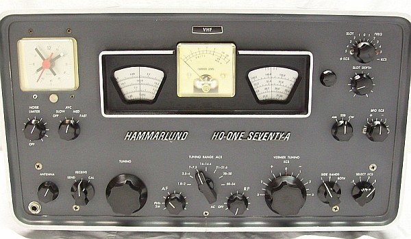
VFO (LO, 455 Kc above signal) 455 Kc IF
VFO (VERNIER, 395 Kc below IF) 60 Kc IF
2 IF amplification stages (455 Kc)
3 IF stages (2 amp + 1 output driver, 60 Kc)
Triple Conversion (by LO setting above)
(40, 20, 15, 10 meter bands)
VFO (LO, 3035 Kc above signal) 3035 Kc IF
2580 Kc XLO (455 Kc below IF) 455 Kc IF
VFO (VERNIER, 395 Kc below
IF) 60 Kc IF
1 IF amplification stage (455 Kc)
3 IF stages (2 amp + 1 output driver, 60 Kc)
Triple Conversion (by LO setting below)
(6 meter band)
VFO (LO, 3035 Kc below signal) 3035 Kc IF
2580 Kc XLO (455 Kc below IF) 455 Kc IF
VFO (VERNIER, 395 Kc below
IF) 60 Kc IF
1 IF amplification stage (455 Kc)
3 IF stages (2 amp + 1 output driver, 60 Kc)
Quadruple Conversion
(2 meter band)
31.333x3 XLO (94 Mc below sig) 52 Mc IF
VFO (LO, 3035 Kc below IF) 3035 Kc IF
2580 Kc XLO (455 Kc below IF) 455 Kc IF
VFO (VERNIER, 395 Kc below IF) 60 Kc IF
2 IF (52 Mc) amp stages (IF amp + RF amp)
1 IF amplification stage (455 Kc)
3 IF stages (2 amp + 1 output driver, 60 Kc)
TUNING
MAIN tuning control for all bands
Smooth operation for lefties
VERNIER TUNING adjusts the Local Oscillator of the 60 Kc converter that controls the exact output frequency to the IF chain. In fact this control is not a vernier tuning, i'ts a PASSBAND TUNING. Very important control to understand the Hammarlund sideband system that requires precise adjustment. A wrong understanding can mislead you and make you take wrong paths.
NOT a tuning control. Permits the adjust of ± 3 Kcs IF passband tuning range. Centered at "0" is for AM/CW. Can be used always at center but not advisable. In order to get accurate reception and centered SSB tuning this control must be turned to + 1.5 for lower sideband (SIDE BANDS at "L" or "BOTH") and - 1.5 for upper sideband (SIDE BANDS at "U" or "BOTH"). This permits coincidence of SSB tuned at peaks on AM position and instant SSB demodulation on SSB position.
Actual PASSBAND TUNING that permits centered adjust on sideband when "L" or "U" are selected. Correct setting of this control is VERY important for the performance of sideband reception; together with the BFO is the "key" of this peculiar system. When it is located at +1.5 (or -1.5) the sideband is being selected to be tuned at center. It can be used for fine tuning, but should not be used this manner habitually, BAND SPREAD tuning is preferable and mandatory for good SSB decoding.
Local Oscillator (LO) drift response
Overall, HQ-170 has a worse drift response than HQ-180. Starting 7 Mcs, drift is noticeable and the stabilization time is about 1 hour, above 21 Mcs it can be up to 2 hours. Hammarlund's solution in model A was to keep the LO and mixer filaments burning 24/7.
Hairline setting knob
Asymmetric positioning on both dials. Not a fault, the vast majority of HQ-170s have this "issue". The HQ-170 is a bands receiver, not a general coverage receiver, it is not mandatory these hairlines must match in position on both dials. It is rare the calibration points of different bands coincide with optimum internal adjusting points at same dial positions.
Local Oscillator (1st mixer) trimmer location
→ HQ-170: Under chassis → HQ-170A: Over chassis
Model A has same LO trimmer location that in models HQ-180
AM detection by...
Diode
Connected to 60 Kc IF output
driver
FM detection by...
Diode, resonance slope, sideband skirt.
Processed by the 60 Kc IF stage.
For to know how this system works go to Home→ES_list
link to page
"El radio '5+1' de AM/FM" and read "Detección de la FM por la pendiente de la respuesta de FI".
FM operation
AM mode VERNIER TUNING at center
SELECT KCS at "3" SIDE BANDS on "L" or U"
The audio quality will depend of the less
vertical skirt of the response curve (the FM detection by signal slope processes
very well human voice when resonance slope is ± 60 degrees).
SSB/CW detection by...
Plate detector, mixer type (double triode
product detector).
BFO and signal are injected
separately to grids.
AVC (AGC) stages controlled
4 = 3 fast + 1 delayed
RF amp (delayed) + 455 Kc
IF amp + 60 Kc mixer + first 60 Kc IF (fast)
AVC switch
OFF, SLOW, MED, FAST positions
FAST for AM/CW reception
AGC on SSB/CW
YES
SLOW, MED/FAST positions
S-Meter on SSB/CW
YES
Sensitive and accurate response
Product Detector
Double triode design type
Excellent performance
Function/Mode switch
→ HQ-170: AM - CW/SSB
→ HQ-170A: AM - SSB - CW
→ AM: BFO OFF. CW/SSB: BFO ON, frequency is
the exact IF when BFO knob is positioned at center. → AM: BFO OFF. SSB: BFO ON, frequency adjusted at
exact IF. CW: BFO ON, frequency is -0.5 Kc off the IF BFO positioned at center, thus rotating to +0.5 the BFO frequency matches again the IF.
BFO KCS control
Range ± 1.9 Kc from
center "0".
+ range: BFO frecuency INcreases.
- range: BFO frequency DEcreases.
→ HQ-170: Works on the CW/SSB position.
→ HQ-170A: Only works on CW, BFO frequency on SSB is fixed, adjusted by T28.
BFO receiving SSB
Hammarlund's system requires the BFO frequency must be the same as the IF, externally or internally, this mean carrier insertion at center of the AM bandpass. → HQ-170: Positioned at center. → HQ-170A: Adjusted internally at exact IF.
"AM-carrier" insertion in the IF 60 KC chain. If the BFO needs to be positioned off center this means the SSB system is disadjusted, but model A disconnects the BFO control on SSB, it only works on CW.
BFO receiving CW
→ HQ-170: Knob positioned to +/-0.5 divisions → HQ-170A: Knob at center (auto -0.5 Kcs IF)
CW signal must de tuned
at zero beat (SSB position), after adjust desired tone. Model A has an exclusive
CW switch position that detunes automatically the BFO from center.
SIDE BANDS switch
L (lower) - U (upper) - BOTH
On BOTH the 1 - 2 - 3 bandwidths of SELEC KCS are doubled.
SELEC KCS switch
.5 - 1 - 2 - 3 Kcs
.5 - 1 Kcs on BOTH/CW
2 - 3 Kcs on L-U/SSB or BOTH/AM
SLOT FREQ control
IF passband null slot on
center position
Range ± 5 Kc center
SLOT DEPTH control
IF slot null level
Maximum depth 20% advanced
NOISE LIMITER control
OFF and ajustable clipping
effect, full wave.
Works in all modes of reception
RF gain control
Includes the power switch
It acts on V1 and V4
SEND
RECEIVE
CAL
Standby/Muting/Transmit relay,
Standard receiving operation.
100 Kc calibrator ON.
SEND position removes 0B2
regulated voltage to VI, V3, V4 screen grids, and V13B plate.
CAL position injects a 100
Kcs signal weakly coupled to antenna connectors.
Operation
with transmitter by...
The J1 relay relay connector
and the AVC connector allows the receiver to be controlled from a transmitter,
or vice-versa, but the combined operation must be studied with care
taking in mind the injection of RF voltage to receiver from transmitter
(an antenna switch is ALWAYS required to avoid BURNING OUT the ANTENNA COILS
in the RF stage). For combined operation the receiver ALWAYS must remain on
SEND position, then J1 is open, but it may be "closed" by external
contacts (external RECEIVE position). → Model A: Relay & AVC in system socket.
EXT RELAY
&
AVC MUTING (VOX silencing,
optional)
SEND position
opens the pins of the J1 power plug on the rear to use them
connected to a set of normally closed contacts of a remote relay, these contacts opens as
relay is being energized so muting the receiver. Main relay contacts
switches the antenna to transmitter.
Relay operation to disconnect antenna from receiver is always mandatory. Also, a terminal on the rear marked AVC is provided to inject in the AVC line an
external DC voltage of -80 to -100 volts to mute the receiver, or to extract AVC
voltage from the receiver to an external accessory.
Antenna control
RF Amplifier sharp tunning
Fine adjust, particularly for model A on 160 & 10 meter bands.
Antenna RF amplifier adjusted by main tuning (tandem)
→ HQ-170: YES (three-section tandem) → HQ-170A: NO (two-section tandem)
The antenna stage of model A requires to be fully adjusted by the ANTENNA control since it does not have any associated tandem section. Model non A has an associated tandem section, so it only requires retouching.
Antenna HF 160-10 meter bands................
Antenna 6 meter band ..............................
Antenna 2 meter band ..............................
SO-239 and terminal strip
RCA phono type connector
RCA phono type connector
-Coaxial or twin lead dipole,
long wire antennas.
-If a combination 6/2 meter
antennas are used, a switch box is needed to disconnect the antenna terminal not in use.
AF gain control & VHF 2 meter converter ON
(also adds an extra 50-54 Mcs RF amp)
To enable the 2-meter receive switch to 50-54 Mcs band and pull out this control and.
AF gain with the Hammarlund auto-response
circuit (simplified Williamson-type feedback).
455 Kc IF output
Weak coupling (10 Pf only) to avoid
misalignment to V3 plate (455 Kc).
Hammarlund says: "coax
fitting 455 Kc output for Q multiplier". This is impossible with this
poor coupling, a Q multiplier needs much more coupling. At the least a
5 Kpf capacitor is needed, and then T3 needs to be readjusted.
Line voltage
115 VAC
115, 230 VAC options in
model A, or non A export model.
Accessories
(1) IF Noise Silencer.
(1) IF Noise Immunizer (the IF Noise Silencer with AGC circuitry).
(2) Telechron Clock Timer.
(1) Can be installed inside.
(2) Can be installed on panel.
Telechron Clock Timer has 3 positions:
ON: Works all the time with receiver on or off.
OFF: Sets receiver to off.
AUTO: Receiver is turned on at desired preset time in the same manner as an alarm clock.
Previoulsy, if the function switch have been settled to "SEND", receiver will remain
standby, this is the usual operation for pre-warming. The small red clock
hand may be retouched in order to obtain exact turning-on of the receiver
at scheduled time.
A 3"/3.2 ohms (4 ohms) speaker may be installed
using the same panel holes provided for the Telechron Clock Timer by means a
DIY adaptation (see the HQ-180 page).
Design values
The actual Intermediate Frequency values may vary based on actual values of fixed frequency components.
Conversion chart sequence [VHFmodel only]
2 meters
VHF amp
VHF mixer
52 Mcs IF
1st mixer High-OUT
3035 Kcs
2nd mixer
455 Kcs
3rd mixer
60 Kcs IF
6 meters
52 Mcs RF
RF amp
1st mixer High-OUT
3035 Kcs
2nd mixer
455 Kcs
3rd mixer
60 Kcs IF
10 meters
RF amp
1st mixer High-OUT
3035 Kcs
2nd mixer
455 Kcs
3rd mixer
60 Kcs IF
15 meters
RF amp
1st mixer High-OUT
3035 Kcs
2nd mixer
455 Kcs
3rd mixer
60 Kcs IF
20 meters
RF amp
1st mixer High-OUT
3035 Kcs
2nd mixer
455 Kcs
3rd mixer
60 Kcs IF
40 meters
RF amp
1st mixer High-OUT
3035 Kcs
2nd mixer
455 Kcs
3rd mixer
60 Kcs IF
80 meters
RF amp
1st mixer Low-OUT
455 Kcs
3rd mixer
60 Kcs IF
160 meters
RF amp
1st mixer Low-OUT
455 Kcs
3rd mixer
60 Kcs IF
Intermediate Frequencies
VHF mixer: 52 Mcs = 146 Mcs - LO at 94 Mcs (3rd harmonic of the 31.33 Local Xtal Oscillator).
VHF model only, wideband amplifier inside the 2-meter converter / 6-meter
IFoutput amplifier). The sideband lettering on panel must be considered reversed.
1st mixer High-OUT: 3035 Kcs = Signal Frequency Received - (LO = SFR + 3035 Kcs) or (LO = SFR - 3035
Kcs in the 6 meter band, sideband lettering on panel must be considered reversed).
1st mixer Low-OUT: 455 Kcs = Signal Frequency Received - (LO = SFR + 455 Kcs). 160 & 80 meters only.
3rd mixer: 60 Kcs = 455 Kcs (2nd IF input) - 395 Kcs (VERNIER TUNING frequency at "0"): SIDEBAND SELECTION stages.
IF output characteristic on rear RCA connector (model A): 455 Kc unamplified, and coupling capacitance is 10 pF only! Located directly at the output (plate) of the second mixer (converter), this is not an standard IF OUT (output of an IF amplifier).
160, 80, 40, 20, 15, 10 meter bands: Sideband inversion; a lower/upper configuration at the input will now become upper/lower at this output.
6 and 2 meter bands: No sideband inversion, sideband positioning is equal to the sideband positioning at the input (antenna RF amp).
Design basis: SIDE BANDS, centers / SELECT KC flatness
KC
Lower position (peak)
Upper position (peak)
BOTH position (peak)
.5
60.000
±60.000
±60.000
1
60.500
59.500
60.000
2
61.000
59.000
60.000
3
61.500
58.500
60.000
Idealized
(theoretical, hard to find in a real unit) Low IF resonances
on respective positions. The ".5" at "L" resonance is the correct BFO
frequency for the SSB position. Usually actual resonance
peaks do not match with this idealized IF passband response chart
due imperfections of centered flatness and symmetrical response.
Lower (internal Upper) sets main IF location at .5 ONLY.
BOTH decreases plate load resistance allowing wide bandpass.
As this chart
shows, the "L" (Lower) panel indication is internally the Upper sideband,
this is due the conversion process. Setting BOTH, the KC offset value is doubled
(except ".5"), and the effective off center shift is less than 1500 Cs due the
system provides overlapping at center. When other combination bandwidth/sideband
is selected the sideband response varies due the action of fixed coupling/tuning
capacitors and loading resistors, if the BFO is adjusted off-center sideband
separation doesn't work correctly. When using the standard model (non A), the BFO
should only be adjusted off-center in order to adjust the CW tone when receiving CW,
ALWAYS must be remembered it needs to be adjusted AGAIN at CENTER for SSB reception.
The model A automatizes this, selecting SSB the BFO frequency is settled down
equal to IF by means of a fixed capacitor that replaces the BFO variable capacitor,
therefore the BFO control only works on CW reception, BUT when CW is
selected the BFO frequency is shifted 0.5 Kcs from the IF, so a CW tone is
automatically generated. As the BFO capacitor works on CW only, this tone may be
corrected using the BFO knob, and when the personalized CW tone is adjusted the
BFO knob can be left permanently on this position, that is, model A permits
an static BFO knob (on model non A it must be shifted for CW), always must be
remembered that in model A the position of the BFO knob has no effect on SSB reception.
The HQ-170 SSB system
is adjusted with the sideband switch at "L" and SELECT KCS at .5 Kc
and it is based on switching different values of capacitors and resistors
that changes sideband bandwidth into the low IF section, thus correct
functioning of the system depends very much on the particular resonance
curve in each sideband. As the sideband switch position "U" (internal
"L" as stated) is tuned-in automatically and corresponds to a circuit
with no previous adjust, this circuit is not optimally adjusted and usually
has less performance than the "L" (internal "U") circuit.
Performance beyond the 0.5 KCS selection depends on the exact values of the capacitors and resistors involved in the selected bandwidth. The Hammarlund HC-10 test page has comparative and expanded info on this SSB receiving system.
Checking the correct operating status of the SSB system:(including VERNIER TUNING corrections, see below)
Select VERNIER TUNING to +/- 1.5 Kc depending sideband,
SIDE BANDS on BOTH, then tune in an SSB signal.
Set selectivity switch at the narrowest bandwidth position (.5), recheck peak setting, and change "L" to "U" and vice-versa:
Tuned signal may be weaker and sounding obscure but should not disappear,
copiable and understandable depending on strength.
Set selectivity switch to 1, 2, and 3 successively selecting sidebands: A LSB signal
on "L" must be received OK, and on "U" must be weak or almost disappear
depending on strength; in like manner, a USB signal on "U" must
be received OK, and on "L" must be heard weaker or almost disappear depending
on its strength.
Trying to show a simplified view on the Hammarlund SSB system: Clearing up misunderstandings on this system.
• The BFO replaces the AM carrier, which is always centered in the IF and between the two sidebands. But the role of VERNIER TUNING is not defined in the manual, it says to set it to "0" and adjusting the other controls as necessary. This doesn't make sense and is easily provable: As the BFO control must remain always at "0", if the VERNIER TUNING control is also at "0", there will not be enough frequency separation when the "X" receiver tunes a SSB signal; BFO and signal will collide at "0"!
• Thus the incoming SSB signal must move and be processed in the corresponding sideband channel, that's why VERNIER TUNING must also be adjusted at one side, not at center, therefore an exact match of IF frequencies (receiver/converter) is mandatory, so the VERNIER TUNING dial reading should be accurate. To reach this:
a) The VERNIER TUNING control must be adjusted to prepare the sideband receiving channel.
b) The incoming sideband must be selected in the IF chain (L-U).
c) Then the SSB signal from receiver "X" can be processed at a selected selectivity (3-2-1-.5).
• The manual does not mention anything about it; it mistakenly refers that the VERNIER TUNING control is a fine frequency adjustment when in fact is a UPPER ↔ BOTH (center) ↔ LOWER operating frequency area selector(tuning concept vs location concept), an exact adjust on its dial is needed.
• When receiving SSB, the VERNIER TUNING control NEVER must remain at center; and when receiving AM/CW the VERNIER TUNING control ALWAYS must remain at center. This control is NOT a clarifier although it may be used as a clarifier, a lot of HQ-170/180 receivers are badly adjusted due manuals do not explain in detail the particular mode of operation of this system, or/and, give counterproductive info.
Operation:
• When receiving AM or CW VERNIER TUNING must be set at '0'.
• When receiving SSB VERNIER TUNING must be set at '+1.5' or '-1.5' (selecting the center of the sideband channel when SELECTIVITY KCS is at '3').
• When receiving SSB, the BFO must ALWAYS be set to '0', this must result in a 60 Kc signal (it may vary a bit).
• BFO must be set '+0.5' or '-0.5' when receiving CW (HQ-170 non A only).
• These positions are NOT randomly adjustable, the only "adjustment" is the MAIN TUNING knob of the receiver, and MAIN TUNING should point to the center of the UPPER, BOTH, or LOWER 'channels'. If the above positions need to be adjusted the SSB system is badly adjusted.
• When a 455 Kc signal enters the converter
a) The VERNIER ADJUSTMENT (L4 coil, the Local Oscillator of the converter) must operate at ±395 Kc (this value may vary depending on the exact IF value resulting from the previous conversions.).
b) SIDE BANDS on BOTH must operate centered at 60 Kc.
c) SELECTIVITY KCS with SIDEBANDS on BOTH must select 3, 2, 1, .5 Kc bandwidths.
d) SIDE BANDS on UPPER or LOWER must select the sideband channel, with SELECTIVITY KCS at '3' it is centered at 1.5 Kc, thus the sideband channels at '3' are 61.5 Kc and 58.5 Kc.
e) If all the above is true HQ-170 will work EXCELLENT.
⇒ KEY INFO: This system works with an UPPER ↔ BOTH (center) ↔ LOWER "template" which is not adjustable in terms of locations, it is only adjustable in terms of width, it is the adjustment of the devices that must adapt to locations.
⇒ The manuals give contradictory or inaccurate information about the system, due this it seems that not even Hammarlund understood it (although it may seem nonsensical and incredible to say).
The best SSB (decoding) setting is the one that matches the MAXIMUM voice movements of the S-Meter needle. SSB decoding with lower movements indicates that the SSB signal is not properly tuned, even though the voice appears to be well decoded and understandable. A different setting will result in differences when making bandwidth selection and sideband selection.
When this system is properly adjusted, the tuning procedure is very similar to tuning an AM signal. If the tuning procedure is critical, or requires adjusting any knob other than MAIN TUNING, the SSB system is not properly adjusted.
VERNIER TUNING is NOT a tuning operator, it is a sideband area selector.
HQ-170 (A-VHF) Tube List and Associated Functions
Function(s)
Tube(s), 16 total
Comments
RF Amplifier
6BZ6 tube (V1)
Delayed AGC
Sensitivity control
Screen grid voltage from VR line
1st Mixer
6BE6 tube (V2)
455 or 3035 Kcs output depending
on band
Dual screen grid voltage from VR line
Local Oscillator (LO, see
table above)
6C4 tube (V12)
Plate voltage from VR line
IF amplifier
2nd Mixer (XLO, see table
above).
6BE6 tube (V3)
455 Kcs IF amplifier on
double Conversion
Mixer on triple Conversion
(455 Kcs output)
Screen grid voltage from VR line
IF Amplifier 455 Kcs
6BA6 tube (V4)
Fast AGC
Sensitivity control
Screen grid voltage from VR line
3rd Mixer
6BE6 tube (V5)
Fast AGC
VERNIER TUNING
IF Amplifier 60 Kcs
6BA6 tube (V6)
SIDE BANDS selection
SELEC KCS selection
IF Amplifier 60 Kcs
6BA6 tube (V7)
SIDE BANDS selection
SELEC KCS selection
IF Output driver-amplifier
60 Kcs
1/3 6BV8 tube (V8A)
SIDE BANDS selection
SELEC KCS selection
Detector
1/3 6BV8 tube (V8B)
AM diode detector
AGC time constant
1/3 6BV8 tube (V8C)
Diode RF rectifier
Product Detector
Full 12AU7 tube (V9)
CW/SSB mixer plate detector
BFO
1/2 12AU7 tube (V13A)
60 Kc oscillator (SSB) 59.5
Kc VFO (CW)
S-Meter amplifier
1/2 12AU7 tube (V13B)
Tube-voltmeter type (simplified)
Noise Limiter
6AL5 tube (V10)
BF adjustable peak clipping
(series type)
Delayed AGC
2/3 6AV6 tube (V15A) → (V16 non A)
Paralleled diodes rectifier
Audio Amplifier
1/3 6AV6 tube (V15B) → (V16 non A)
Triode audio preamplifier
Audio Power Output
6AQ5 tube (V16) → (V17 non A)
Pentode audio power amplifier
Power AC Rectifier
Two silicon diodes (1N4007
type)
AC full wave rectifier → (5U4 - V15, non A)
Calibrator
6BZ6 tube (V11)
100 Kc Xtal oscillator, B+ is from VR line.
Voltage Regulator
OB2 tube (V14)
VR tube, 108 volts, VR line source
VHF 2 Meter Converter
4 tubes
Wideband Converter
RF Amplifier
6CW4 nuvistor tube (V201)
2 meter band antenna input
VHF Mixer
6CW4 nuvistor tube (V202)
146 Mc input, 52 Mc output
Local Oscillator (see
table above)
6CW4 nuvistor tube (V204)
31.333 Mc Xtal oscillator,
94 Mc tuned output
IF amplifier, 52 Mcs.
6CW4 nuvistor tube (V203)
6 meter band: antenna connects to its input.
Contents
Concluding overview
Top of the line receiver for Ham bands, but don't forget about the warm-up time. Excellent performance, sensitivity only a bit less
than its 'big brother' the HQ-180. Don't to be confused about the VERNIER TUNING, not a clarifier even though it may be used that manner. This control adjusts the local VFO of the last mixer (input of the sideband selection), it must be settled at 0 Kcs for AM-CW, about +1.5 for LSB, and -1.5 for USB. The HQ-170 is an excellent receiver for Ham bands, it does not require major improvements, just touch-ups, if something goes wrong suspect a failure not a design defect. Very good to excellent sensitivity, excellent selectivity when the L and U sideband positions are selected, very good signal to noise ratio, easy SSB tuning if the BFO is at center and the "VERNIER" control has been adjusted +1.5/-1.5, communications quality audio (not HI-FI of course, as it should be), and very good to good LO stability depending on frecuency range after a short warm-up time. Model A includes a bizarre modification: V2 and V12 tubes (1st mixer tubes) stays burning even when the radio is off, during the service job the transformer for those tubes was re-routed to go out with the rest of the circuit. The manufacturer's purpose was to increase frequency stability by eliminating warm-up time, but this arrangement is only practical if the receiver is used very often, otherwise it will cause meaningless filament wear. So when purchasing model A, the first thing to do is check tubes V2 & V12 in a reliable tube tester since these tubes are essential in performance of any superheterodyne receiver. Model non A has standard filament configuration, which is better. The HQ-170 is a classic, but updated, ham bands communication receiver, it can be used routinely today. Like all high-selectivity receivers, audio response is designed to match IF response, which is also designed to receive voice communications in adverse conditions, not to receive under commercial broadcasting criteria, thus the HQ-170 may not be suitable for Hams liking audio HI-FI performances and wide compatibility, to achieve this, better choose a general coverage radio with less selectivity requirements, the HQ-160 for example.

 link to page
"El radio '5+1' de AM/FM" and read "Detección de la FM por la pendiente de la respuesta de FI".
link to page
"El radio '5+1' de AM/FM" and read "Detección de la FM por la pendiente de la respuesta de FI".