URM-25D Signal Generator Overhaul
|
Contents Introduction. Pros and Cons. Modulation oscillator. Buffer-Amplifier-Meter. |
Crystal Calibrator. Oscillator-Dial-Attenuator. Power Supply and AC line. Schematic and Terminal Board. Back to URM-25D main page. |
Introduction
The URM-25D manual summarizes on describing operational steps in order to overhaul URM-25 circuits and sub-assemblies, thus I suspect that in the army overhaul centers should exist an extended service manual to fill this gap. About 30 years ago, Dallas Lankford(1) writed a useful guidance(2) about overhauling URM-25Ds that is a good help because a URM-25 looks somewhat cryptic due to its architecture. The intention of this page and the following is expanding and updating these notes.
Looking inside this URM-25D, it has drawn my attention that cables and component leads, prior to being soldered, have been virtually "sewn" to pins and terminals (winding several times, passing inside and out, and tightened with pliers), IMO this is excessive and redundant, thus on refurbishing an "unsewn work" is required if good soldering practices are used (as Dallas Lankford suggests), "good soldering practices" implies to remove entirely the old capacitor, including wire portions soldered to pins.
I don't like making changes for no specific reason, but in a URM-25 complete replacement of the Micamold brand waxed capacitors is mandatory since the original ones are the worst (IMO) that withstand the passage of time (do not associate Micamold brand with mica dielectric). Unfortunately it is totally unavoidable, I also don't like to replace capacitors "by default", but these capacitors are characterized by having high levels of leakage, probably the highest aging leakage level found on vintage waxed paper capacitor manufacturing. This always must be taked into account on a URM-25 overhaul or purchase evaluation because a non-overhauled URM-25 will rarely work OK although it seems so (bias tend to be less negative, this wears out tubes prematurely and overloads the PS transformer). URM-25Ds and URM-25F have "uncomfortable" component locations, so this makes the URM-25D overhaul a time consuming experience that requires patience and meticulousness. A URM-25D has 9 waxed paper capacitors that need to be mandatory replaced, what seems little, but due to the "bad" location, and the "messy" circuit architecture difficults the job.
There are two types or paper capacitors in a "standard" URM-25D: Waxed Paper capacitors (paraffin), and Paper In Oil capacitors (PIO, they have some electrolytic appearance). The first ones are Micamold brand, the second ones are Gudeman brand (BTW, this signal generator is an excellent example about the popular topic of which paper capacitors need to be replaced and which ones don't). Also there are both mica and paper Micamold brand capacitors, the mica ones are all (usually) good, the paper ones are all bad (for sure). The installed Gudeman capacitors also are paper capacitors, but they are paper in oil (PIO), usually all of these are OK. Power supply filter capacitors (3 units of 4 µF) are Sangamo paper in oil, that also are usually OK.
Micamold brand paraffin waxed paper capacitors to be replaced, 9 of 3 values:
5 of 0.01 µF 300 V (C130, C155, C159, C164, C165), 2 of 0.1 µF 400V (C162, C163), and 2 of 0.2 µF 120V (C166, C167).
Actual normalized values are: 0.01 µF 400V, 0.1 µF 400V, and 0.22 µF 160V.
 |
 |
 )
)Pros and Cons about purchasing/refurbishing a URM-25
- Pros, only one but important:
- • You will own a signal generator that is close in performance to tube lab generators and, by connecting a digital frequency counter to X-200K or X-MULT RF outputs, competitive with modern generators. The URM-25D's reduction gear and the always-adjustable signal level allow for relatively easy adjustment on the digital dial of a frequency counter of any frequency in ALL ranges; and that can't be said for many vintage generators (difficult in HF ranges).
- Cons, everything else:
- • A URM-25D requires mandatory total replacement of the waxed-type paper capacitors. The Micamold paper capacitors (not to be confused with mica dielectric) installed in URM-25Ds are very well built "mechanically" (see pic above), but also are the worst capacitors to stand the test of time (is it due to its squashed shape?).
- • The URM-25D architectural design is the result of a kind of balance between available space, inter-circuit linking, operational needs, and performance, resulting all in a kind of mechanical/electrical puzzle, thus repairing or refurbishing a URM 25 is not comfortable, will require skill, patience, and time.
- • As with all devices of military origin (or that have had intensive professional use), it must be assumed they may have wear, mistreatment, quick n' dirty repairs, accordingly, hidden problems, thus be careful on paying some amounts that are requested on eBay, if you cannot do the work DIY-style a URM-25 purchase is not recommended, and if you can do it, IMO the inevitable overhaul work must be "substracted" from the bid or purchase value.
- • Although defined as "portable" a URM-25 is a heavy machine. A signal generator is a frequently used device, and sometimes needs to be placed near the equipment being tested; the reverse may be impractical or cumbersome. I do not restore to collect but to use, when the wall is 230 volts and the device is 115 volts the need to use a step-down transformer always causes operational discomfort, thus, a warning for "no-115/125 VAC people" who buy vintage equipment to use and not for decorative purposes: IMO it should be taken into account that 115 volt-only devices to be used in "no-115/125 countries" are OK only when they have low amperage drain (e.g. a grid-dip) because they allow to be connected to mains via these small 230/115 cord plug-in transformers, but the URM-25 is not one of these devices, its use via step-down transformer may not be practical, annoying for sure. Better that it can be connected to standard mains outlets, due this consideration the power supply of this unit has been modified to run on 230 volt mains.
Modulation Oscillator circuit overhaul
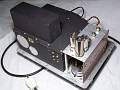
7 waxed paper Micamold capacitors need to be replaced in this subchassis (C159, C162, C163, C164, C165, C166, C167). Working on this board requires attention, and a lot of patience if good soldering practices are used.
- Dallas says the entire modulation subframe should be removed, but this extra work can be avoided operating with care, thereby it is unnecessary un/soldering leads and un/screwing more screws. Removing this subchassis from rear of front panel adds more work to obtain little benefit, all subchassis elements are interconnected by some leads, unsoldering these leads only add risk of mistakes, IMO better avoid it.
- Remove V106, V107, and V108 tubes.
- To make accessible the modulator/AF-oscillator compartment remove the 4 screws that holds in place the tubes and potentionometers plate.
- Remove the 4 screws that attach the "printed-circuit" terminal board to the assembly bars.
- Slip the terminal board by the support bars (there are some wires over the bars).
- Unplug the internal BNC from the step attenuator in order to make more room.
- Open like a book the tubes board from the terminal board in order to replace C163, C162, C164.
- To maintain the "book" open, a docked bar may help (see pic # 4, on the left).
- Reverse/relocate board positions and replace C159, C165, C166, and C167.
- Do not reinstall the boards, to release the next subchassis that is inside the shielded compartment, these boards must remain loose.
Reverse steps for mounting.
Buffer-Amplifier-Meter subchassis removal and overhaul
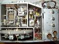
Only 1 paper Micamold capacitor needs to be replaced in this subchassis, C130 (0.01 µF 300V paper in molded phenolic case), but this is the one that requires more time and work.
- Remove carrier range (10-300Kc / 300Kc-50Mc) switch knob and MICROVOLTS control knob.
- In order to make accessible the circuits that are in the shielded housing (to replace C130 and C155) remove the 17 screws that hols in place the oscillator/buffer/calibrator compartment cover plate.
- Remove 6AG7 tube: with an screwdriver loose the safety clamp, after pull the tube using a screwdriver between tubesocket and tubebase, operate step to step and side by side, when 6AG7 is removed, 6AL6 and 6AH6 tubes can be removed more easily.
- Unsolder:
- The short wire from pin 1 of V102 (6AH6) to the feedtrough.
- The lead of the R130 resistor connected to the BNC lug used to connect the step attenuator.
- The lead of the R129 resitor connected to the BNC lug RF OUTPUT/X-200K/OPEN CIRCUIT.
- Remove:
- 2 side screws entering from the modulation oscillator side.
- The BNC female used to connect the step attenuator. To do this, do NOT force the BNC cylinder to unscrew it, as Dallas aptly says, the correct procedure: connect a BNC male to this BNC female, and after applying pliers to the BNC male unscrew the BNC female. Pic # 11 shows the BNC female removed with the BNC male plugged-in.
- 1 screw at bottom (next to the BNC RF OUTPUT).
- (Optional) There is a terminals bracket upper the chokes bracket (pic # 09), if it is unscrewed, subchassis leads will be a little longer.
- Unscrew until free but leave it in place:
- 1 medium screw at bottom, under the chokes bracket, removing the upper bracket (read above) there is more room to operate.
- 1 medium bottom screw that is between V104 (6AL6) and the BNC lug.
- Save these two screws. Note: before re-installing the subchassis these screws MUST be previously inserted into chassis holes as it is very difficult to do this with the subchassis located in place.
- The subchassis can be removed pulling up with lateral movement. If remains a bit locked this is due by the end of the switch shaft, use a screwdriwer to pull inside the switch shaft from the subchassis frame.
- Place the subframe on top of a light wood sheet as shown in the pic # 11, this avoids disconnecting leads and permits to work with some comfort. If the bracket described above has been removed, these cables will be longer and the refurbishing operation will be more comfortable.
- C130 (10K 300V), Micamold paper in molded case must be replaced.
- Perform a leak test to check the overall quality of the rest of the capacitors.
- Check C139 (20K 100V) on a condenser checker like the Heathkit C-3 or similar. It CAN be checked in-circuit by placing the carrier range switch in a position other than 10-300. This capacitor is of the PIO type, check value, leakage, and load/unload capacity. If the result is reasonably good (it's usually like that), the C133 capacitor can also be considered good due it is identical.
- Check C140 (250K 400V) Gudeman PIO tubular by unsoldering its connection to the solder point with R33 (the easiest check point). If it is not leaky, it is very likely that C129, which is identical, is also good. C134 (100K 100V) is of the same type and lower capacity, if C140 is good, C134 can also be considered good.
- Usually PIOs are fine, otherwise the work gets complicated. Only one PIO was replaced in this unit (C139), and not because it gave bad test, but because its weird external appearance, see pic # 12, BTW, note the "sewn length" in the C139 leads, it was replaced by the brown one that you can see on the left (plastic dielectric).
Reverse steps for mounting.
Crystal Calibrator subchassis removal and overhaul
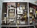
Only C155 (Micamold, 0.01 µF 300V paper in molded phenolic case) needs to be replaced in this subchassis, very uncomfortable to work because the leads of this subchassis are a bit short.
- Unsolder the R176 lead to the feedtrough.
- Unsolder the C119 lead to the feedtrough.
- Unscrew and remove the standoff insulator.
- Remove V105 tube.
- Unscrew the 2 front panel screws which attach firmly the AC filter case and the AC cable to the front panel, lift up AC filter case.
- Unscrew the 2 screws that are behind the AC filter.
- With the aid of a tube shield lift up the Cristal calibrator Subchasis and locate it over the tuning capacitor (see pic # 15), C155 is now accesible, cables from bottom are too short, they do not permit to make the same procedure done with the previous subchassis.
- Using here "good soldering practices" may be counterproductive since it requires too much intervention in the welding points (tube socket terminals), especially if before soldering a "sewing" work was made. Appraise here a method to avoid forcing tube socket pins or "printed circuit" terminals:
- Cut the C155 Micamold capacitor leads just next to its molded case.
- Make small rings in the new C155 capacitor (BTW, you don't need to use a 1 KiloVolt capacitor like Dallas Lankford did, 400 volts is enough) next to its body using a portion of its leads (that is, adding "terminals" to the capacitor).
- Solder the old C155 capacitor leads into the capacitor rings (see pic # 16). Probably this method is the best method (clean, fast, safe) to replace capacitors in URM-25s (D-F).
Reverse steps for mounting.
Oscillator subchassis - Dial - Step Attenuator
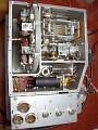
- The oscillator sub-chassis does not have waxed paper capacitors, thus does not require inspection, only the usual check for tube activity that must be applied to all subframes.
- Oscillator is composed by the 6AH6 (V101) tube circuit and a set of interchangeable coils provided by a rotary turret band change switch system (see locations in pic # 17 and detail in pic # 18).
- The dial cover can be removed for inspection, as seen in pic # 19, removing the 4 screws from the corners of the cover.
- The RF MULTIPLIER, a reverse labeled output attenuator (pic # 20), can be removed and inspected separately (Note: In model F the attenuator is an integral part of the front panel, it can be inspected but not removed).
Power Supply & Mains update for "no-115/125 VAC" users
A practical feature of a signal generator is that it can be relocated on the workshop table or it can be moved closer to other devices, thus it must be able to be connected to any wall socket, but a URM-25 only can to be plugged into a 115 VAC mains, and it has 48W of consumption, the use of a small plug-in cord transformer is not possible. In order to have comfortable use in countries that have a mains voltage other than 115/125 VAC, it is almost mandatory to replace the original transformer, since transporting heavy gear together with a heavy step-down transformer is not practical.
There are two families of URM-25Ds regarding type of transformer: Those that do not have a secondary to supply a regulated voltage circuit board (to filament of oscillator tube), and those that do. Standard models do not have this special secondary. Owning the standard model is an advantage in order to replace the original transformer due the amperage drain of a standard URM-25D is very similar to the popular 5/6/7-tube AM/FM receiver (transformer version); so any PS transformer salvaged from these radios is suitable for a standard URM-25D.
A collateral advantage of replacing the original transformer with a receiver-type transformer is that a "design flaw" can be corrected. There is only one filament line in original transformer, therefore the rectifier tube filament is connected in parallel with the rest of the filaments. If a cathode-to-filament leak occurs in the rectifier tube, all the filaments of rest of tubes would melt at once (and there are also other negative aspects of sharing rectifier filament lines with the rest of the filaments).
- A URM-25D has 9 tubes regarding DC voltage, and 8 filaments regarding AC voltage. Total consumption is similar to AM/FM commercial tube radios since the audio power tube consumes twice that the "final" tube of the URM-25. The filament line fits a bit fair but it is OK taking into account that the rectifier tube no longer counts because now it is fed separately.
- A salvaged commercial radio transformer has been used to replace original transformer. It was only necessary to adapt a little the mounting holes of the original transformer, both have similar dimensions, the radio-type is a little wider, see pic # 23.
- The receiver-type transformer was installed on the chassis using 4 brackets (pic # 24). Filament of the rectifier tube now works separated from the rest of filaments (pic # 25).
- Dallas says that many of the URM-25s' AC input filters were "fried", pic # 27 may be an example of a refurbished filter. This was already been repaired in the army services, values of the replaced chokes are not the same as those defined in the manual, thus indicating design values are not critical. He also refers to the mod to avoid breaking the feedtrough filter capacitors, which has already been done in this filter. Pic # 28 shows an original filter to compare.
- These type of filters are not only used to work on any RF entering through the mains line, it is primarily designed to filter out any outgoing radiation that may flow from the signal generator, and consequently that may be emitted by the mains cable.
- This unit came without the fuse caps due there was an intermittent short in the neon lamp resistor (100,000 ohms), I guess that's why the caps were removed. When changing to 230 VAC, the value of this resistor must be double. See the integrated-type neon lamp holder disassembly in pic # 29, and its repair/adaptation in pic # 30.
- B+ consumption of this modified URM-25D standard model is 57 mA. Total consumption in mains cable is 210 mA, so 230 V x 0.21 A = 48.3 W, exactly what the spec says.
URM-25D Schematic suitable for printing and Terminal Board description
 |
 |
 |
 |
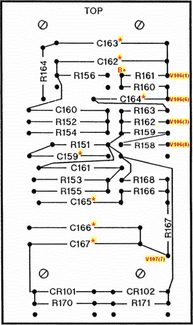 |
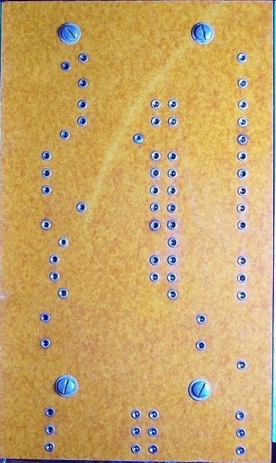
| Terminal board, eyelet side. | B+ DC input to board. * Micamold paper. () tube pin#. |


