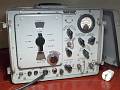
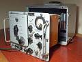
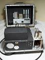
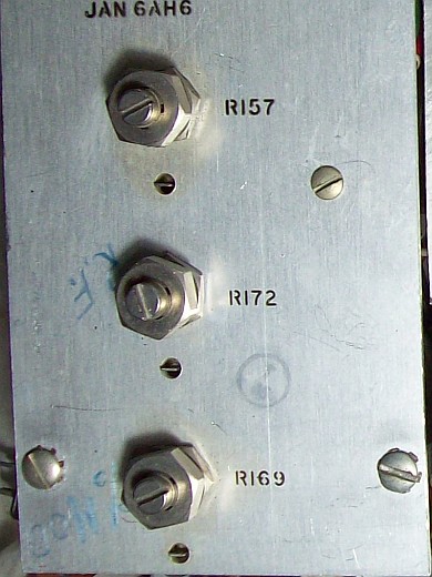
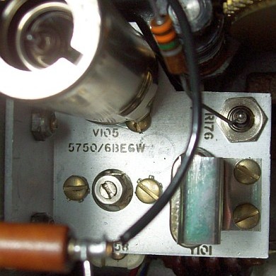
Output voltages and meter adjustment (Refer to the picture above)
R157 (modulation oscillator feedback adjust, AF signal):
• Plate to cathode of previous tube signal feedback adjust, AF signal
distortion corrector, similar to the used in HI-FI preamplifiers, the
feedback effect must be controlled by means of an oscilloscope. It should only be readjusted in the presence of AF distortion.
R172 (RF output voltage calibration and meter reading equivalence):
• MICROVOLTS to fully clockwise position (MAX).
• CARRIER to fully counterclockwise position (MIN).
• METER READS to CARRIER-CW (MOD XTAL & METER SELECTOR).
• Set frequency at 100 Kc.
• Set carrier range response to 10KC-300KC X-200K
• Connect an AC voltmeter to RF OUT X-200K OPEN CIRCUIT (with NO EXTERNAL load at RF OUTPUT X-MULT).
• Rotate CARRIER until 2.0 volts are indicated on the AC
voltmeter, the signal generator meter should read "10" microvolts (upper
scale). This "10" = 2 volts at the X-200K BNC (10 µV x 200,000 = 2
volts). If not, adjust R172 until the signal generator meter reads "10", the AC voltmeter also should reads 2.0 volts.
• To maintain calibrated output when selecting a new VFO test
frequency, follow the procedures described at bottom in the URM-25D main
page.
The URM-25D's adjusting principle is that the signal
generator is separated from the output attenuator (RF MULTIPLIER). The output voltage to be "processed" is the one before the
attenuator and over a 555.55 ohms load (RF OUTPUT X-200K), therefore any discrepancy in the RF
OUTPUT X-MULT BNC will show a fault in the attenuator discarding previous circuits. This
is the procedure stated in the manual, IMO is very good. Dallas refers
the adjustment to RF OUTPUT X-MULT, which may be risky, output may be
OK, but the attenuator may disguise a possible fault.
At this point, the URM-25 applies math to these 2 volts OPEN CIRCUIT for accurate output at RF OUTPUT X-MULT via RF MULTIPLIER:
a) The attenuator is a ladder-shaped pi-type stepping attenuator.
b) Attenuator is connected in series at the end of a 500 ohm resistor.
c) Input of the attenuator has an ohmic value of 55.55 ohms.
d) 500 ohm resistor / 55.55 = 9 parts of 55.55 ohms of value.
e) 9 parts of 55.55 + 55.55 (input of the attenuator) = 10 parts of 55.55, the attenuator is connected at the end, thus 2 volts in 10 parts = 0.2 volts each part.
f) When the matching (should-be) external 50 ohm load is connected to RF OUTPUT X-MULT (BNC output of attenuator), voltage in this BNC divide by 2, so 50 ohms internal (output of the attenuator) with 50 ohms external (load) in parallel increases amperage but
reduces voltage, thus 0.2 / 2 = 0.1 volts = 100 mV = 100,000 µV.
Dallas applies all
of the above directly (see drawing in his notes) by
connecting a 50 Ohm load (0.2 / 2 = 100 mV) followed by an oscilloscope
or a RMS voltmeter to measure. Instead 100 Kc he uses 1Mhz, which IMO is a bit high to get consistency.
R169 (percentage of modulation calibration):
• Set frequency at 100 Kc.
• METER READS to %MOD-400 (MOD XTAL & METER SELECTOR).
• Set carrier range response to 10KC-300KC position.
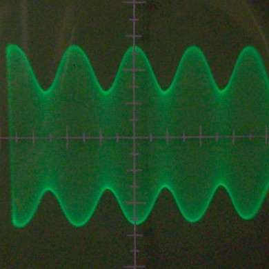
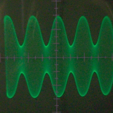
• Connect an oscilloscope to RF OUTPUT X-MULT, select a sweep frequency lower than modulating frequency.
• A graduated celluloid screen must be placed on the oscilloscope tube.
• With RF MULTIPLIER switch and MICROVOLTS adjust the modulated signal amplitude.
• Adjust %MOD AUDIO OUT until 50% modulation is indicated on the oscilloscope.
• Adjust R169 until the meter also indicates 50% modulation (lower scale).
• Adjust %MOD AUDIO OUT until 30% modulation is indicated on the oscilloscope.
• Check reading on the meter. If necessary readjust R169 until 30%
and 50% readings are both accurate as possible, favoring 30% since this
value is considered the standard for adjusting carrier percentual
modulations.
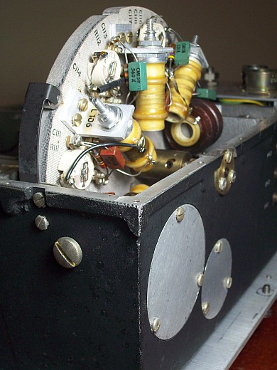
VFO frequency adjust (rotary turret band change coil adjust)
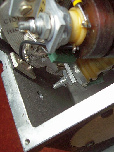
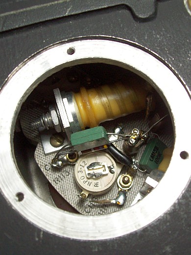
Turret access is accomplished by removing the big screw and the large circular plate
Thick screw removed to make INDUCTANCE adjustment.
Large plate removed to make CAPACITANCE adjustment.
The procedure shown here is not the zero beat procedure stated in the manual, neither the procedure stated in Dallas notes, it is the modern procedure based on checking frequency using a digital frequency counter.
Important note:
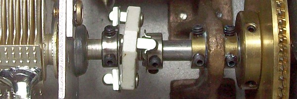
The URM-25D dial drag and gearbox mechanism has a peculiar behavior that is not due to a malfunction of the anti-backlash gear, it is due to the inevitable mechanical stress of the flexible shaft adapter (below) that interconnects the anti-backlash gear shaft to the variable capacitor shaft. This adapter must interconnect two shafts with different axis of symmetry correcting this way mechanical assembling tolerances. The result is that the dragging stress is not symmetrical when rotating clockwise then counterclockwise, this causes invisible discrepancies in dial accuracy depending on direction of rotation. At time of manufacturing, this "peculiarities" were considered admissible tolerances, remaining hidden, but nowadays these tolerances are revealed when a digital counter is placed at the output. This behavior is more noticeable in the high range of each band because a small mechanical variation represents greater frequency variation.
Adapter that joins two shafts with different axis of symmetry.
Previous considerations:
• There are two aspects on tweaking a resonant
frequency of a tuned tank: Coil and Capacitor. Usual
sequence is to adjust first the low frequency range with the
coil slug, and after the high range with the trimmer capacitor. This is
presented as the complete solution, but a little commented side is that
frequency adjustment will be the same both per coil
slug than by trimmer capacitor due coil and capacitor are in parallel (it would only be different if the
trimmer were a padder, which is a series capacitor).
• This is the case in a URM-25. When a trimmer
is in parallel to a coil, core slug (coil) adjustment is usually a coarse adjustment, and trimer adjustment is fine
adjustment. The result is that if the core is adjusted carefully and
precisely, it is not necessary to touch up the trimmer.
Therefore, only in the case that the frequency is very mismatched would it be necessary to touch up the core of the coil and trim the capacitor. To simply do a touch up, you can easily choose just one of the two.
• Trimmer is ceramic, ceramic trimmers can give surprises ("frozen"
or aged contact areas), so I recommend to choose the coil core (slug),
in this case it is only necessary to remove the large screw to insert a screwdriver-type
insulated shaft into the screw groove that drives the coil core and
shown in the photo above (compartment is now closed, so in the "dark" a
little patience may be needed).
• If you want to touch up the trimmer remove the large plate, but keep in mind this plate has to be put back
(without screwing it again of course) EVERY TIME the settled frequency is
being checked (frequency lows if the hole is left open).
Adjusting process:
Wait for a 15/20-min warm-up period (if the URM-25D is well overhauled no more time is needed).
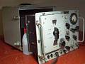
• Arrange the URM-25D as in the second picture of the series shown on page top.
• Remove the lateral BIG screw.
• Set lower range (10-30KC, the least affected by temperature), and choose frequency to check in that
range.
• Set carrier response adjust to 10-300KC. When adjusting ranges up from 300 KC select 300-50MC.
• Connect a digital frequency counter to RF OUTPUT X-MULT (RF MULTIPLIER output) setting RF MULTIPLIER to X10K. It can be connected to RF OUTPUT X-200K, to do this the carrier response selector must be located on the X-200K shared section. Using this BNC must be taken into account that any load in this location may reduce meter reading.
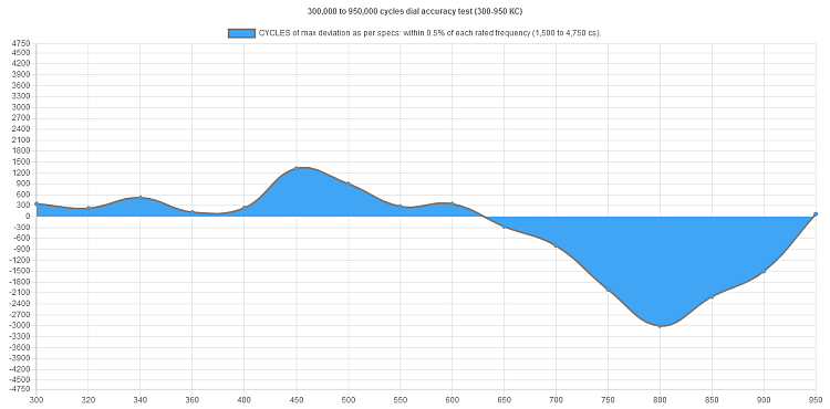
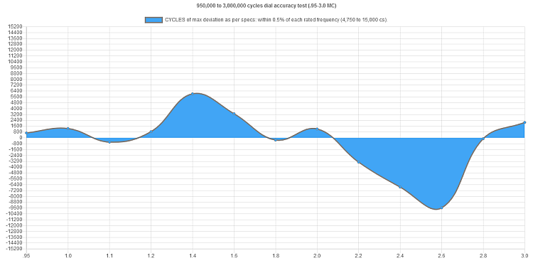
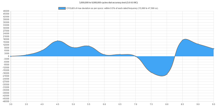
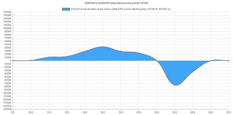
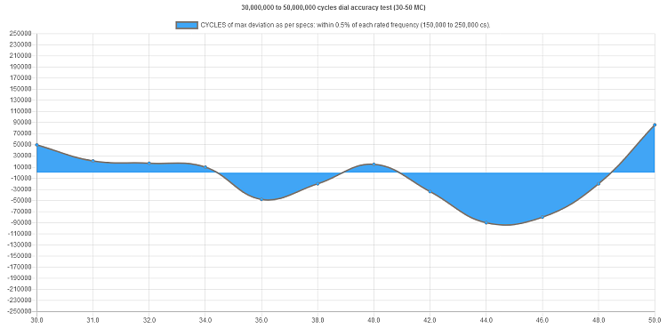
• Minimum frequencies to be checked must be 3 for each range
(low, medium, high), so as there are 8 ranges, 24 frequencies will be
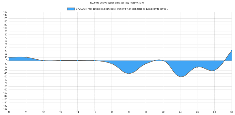
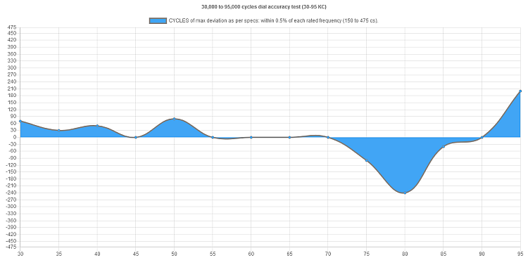
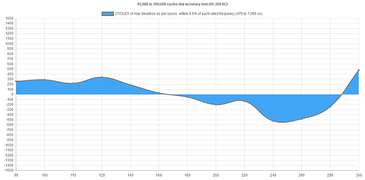
checked. A more complete study can be done by drawing response curves to
verify tolerances (see below).
• Band adjustment must be done choosing the mean value of an
imaginary line between these three values, this assure a balanced adjust and adequate
accuracy for each frequency.
• Do the same procedure on the rest of ranges.
• Power OFF, and after 24 hours recheck accuracy. A URM-25D well
overhauled remains within manufacturing specs easy and seamlessly,
reinstall removed parts if any, and it can be put fully back into the
case.
Nowadays frequencies can be checked very easily and accurately by
means of a frequency counter. Frequency counters have made
frequency-standard generators and most beat calibration procedures obsolete. The
original use of this crystal calibrator is outdated, but it is still a 1 Mhz RF source!
The updated use of this calibrator is now to have a calibrated signal of 1 Mhz, not an internal beat oscillator,
so it can be used as an additional frequency output in a URM-25.
As an example, it may be used like a frequency calibrator in receivers
for high frequency bands, where the standard 100 kc signal
from the receiver does not have enough marking clearance on its
dials, creating confusion as to which is the correct dial mark, the one on the left or the one on the right?
The procedure to adjust it to an exact 1 Mhz is the same as to adjust a
receiver calibrator. Simply put a frequency counter at the output and
adjust the C158 trimmer (see pic on the left) for an exact output of
1,000,000 cycles. The step-by-step procedure to use the URM-25D xtal calibrator as 1 Mhz
frequency standard generator, and also making the adjust by frequency check, is explained at bottom of the URM-25 main page.