|
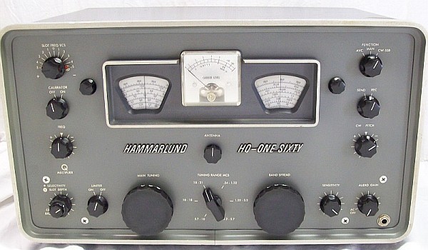
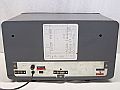
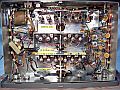
The Hammarlund HQ-160 is an intermediate model among the models with large case (HQ-145, HQ-170, HQ-180), companion of the small case models (HQ-100, HQ-105TR, HQ-110), and a direct heir of the classic HQ's (HQ-120, HQ-129, HQ-140, HQ-150). HQ-160 has three schematic editions and three Hammarlund-model label designs on the front panel. Earlier production has two styles of lettering painted on the front panel (1940s style the first and 50s style the second), last production (like the unit shown) has attached molded plastic cursive lettering.
Manufactured since 1957 to 1959, the HQ-160 has 13 tubes and gives continuous coverage from 540 Kcs to 31 Mcs in six bands: .54-1.32 Mcs, 1.32-3.2 Mcs, 3.2-5.7 Mcs, 5.7-10 Mcs, 10-18 Mcs, and 18-31 Mcs.
Simple conversion up to 10 Mcs with three intermediate frequency amplification stages (455Kcs). Double conversion starts from 10 Mcs (1st IF 3035Kcs, 2nd IF 455Kcs) with two amplifier stages in the last IF.
Selectivity is adjustable via a Q multiplier circuit, works great, both on AM and SSB/CW. The main characteristic of this type of circuit is that it narrows the passband (especially at peak) and simultaneously increases sensitivity. This is a regenerative type circuit, it could be considered obsolete or a rarity compared with the phasing type crystal filter, but in fact it results more practical than the phasing circuit due to this double effect. Passband narrowing with this circuit (which can reach values as low as 100 cycles) has a slope far from vertical, the slope verticalizes only in the last section (peak), so an "attached signal" always will be heard with more or less intensity, but with the phasing circuit occurs the same, and the phasing circuit does not increase sensitivity since it is a passive circuit.
To aid on interfering signal reduction, it has a slot filter that covers the entire IF passband, and whose frequency and depth can be adjusted on the front panel, but, as usual in this type of circuits, it is very effective for interfering carrier suppression (CW) but much less effective for modulated carriers (AM, SSB). To assist on noise reduction, it has a series circuit that can be connected to ON/OFF, which is included in the AM detector, so it only works on AM.
It has a pentode-type product detector so-called linear (this may cause confusion) that works very well. SSB signals are demodulated by inserting the BFO "carrier" suitably shifted to the '+' and '-' BFO dial marks (+/- symbols refer to higher/lower BFO frequencies). With this, the BFO signal creates an "AM carrier" in the center of the IF. The first conversion is based on higher frequency, thus side bands are reversed, the '+' BFO marks are for USB, and the '-' marks are for LSB in all ranges up to 10 Mcs. From 10 Mcs there is double conversion and this second conversion is also done by higher frequency, therefore sidebands are reversed again, leaving '+' for LSB and '-' for USB in all ranges from 10 Mcs. As SSB emissions up to 10 Mcs are in LSB and from there in USB, this reversal makes an "automatic sync" with the HQ-160 heterodyne conversion scheme, resulting in a very comfortable reception on amateur radio bands: The usual +/- BFO adjust is unnecessary, the BFO knob always remains positioned on '-'. Optimal offset for SSB is between 1200 to 1500 cycles (about 3/4 dial marks from the center mark).
Number of stages under AGC are 2 (1 RF + 1 IF), too few. Experience says that in a communications receiver at least 3 IF stages are necessary (3 IF stages + 1 RF is the best for SSB), but here in the CW-SSB position AGC and S-Meter are both disconnected, operation is performed "old style": SENSITIVITY is placed in a moderate position that guarantees a good reception (to avoid saturation of the detector on strong signals) and signal level is increased operating AUDIO-GAIN. This mode of operation is now obsolete due the modification accomplished that also adds an IF stage into the AGC line, operation of this receiver results greatly improved, both on AM and SSB.
Accurate frequency reading combined with fine tuning is more easy with the HQ-160 than on other hammarlunds because the main dial has adjustable hairline, this permits to use the bandpread dial for calibrated fine tuning, this is, to explore accurately any group of frequencies of the main dial. The procedure consists on marking the calibrated starting frequency with the hairline in the main dial, and then using the bandspread dial as a vernier (relative frequency marker).
A comparative example; spreading the 14 Mc band using two methods of fine tuning:
- a) Set main dial to the 14 Mc band high frequency marker and use the bandspread dial. This is the standard procedure as the 14 Mc band is already spreaded in the bandspread dial.
- b) Main dial to 14.000 with hairline at center, bandspread dial to 14.350 (may be other but beware with the 100 Kc calibrating mistake), calibrator ON, then adjust main dial to zero beat, set again 14.000 Mc using the hairline knob (hairline at left), calibrator OFF, tune with main dial, when the received station is tuned OK the bandspread dial may be used for fine tuning (SSB/CW, AM is unnecessary); the frequency shift from 14.350 of the bandspread dial must be added to the frequency reading of the main dial if the reading is less than 14.350 and added when greater; if the bandspread dial is used must be "zeroed" at 14.350 again before the main dial tunes another station.
The CB range does not have bandspread marking, but a bandspread option for this range may be accomplished locating Main Tuning over the 28,5 Mcs mark of the main dial, then CB band spreads from 28 to 29.150 Mcs on the Band Spread dial (megacycle reading will be +1 Mhz and frequency error will increase as tuning increases, but this procedure results handy).
The HQ-160's double conversion system layout
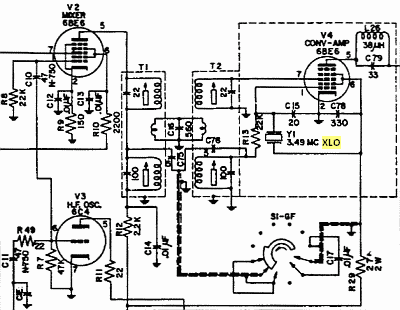
HQ-160 double conversion design (S1 switch selecting 18-31 operation). |
Hammarlund's popular and ingenious combined double conversion layout on the left. A heptode (V2) and a separate triode (V3) as LO make up the first conversion; another heptode (V4) with an XLO constitutes the second conversion. The converter tube (V4) works as an IF amplifier on single conversion ranges, and as a true converter on double conversion ranges.
Schematic shows the high IF coils of T1 and T2 at top (bottom in real transformer), they only work in double conversion ranges. Coils at bottom are tuned to the low IF, so they only work in single conversion ranges. Both circuits are coupled by a link. This link works only on double conversion ranges due it is located next to the high frequency coils in both transformers.
But unfortunately, the HQ-160 converter section (V4) has a design FLAW (*) that causes the signals generated by the XLO to be introduced into the rest of the circuits. This will be more important the less capacitance C78 has, and the less "clean" the signal generated by the XLO is. |
| Switch S1 manages the number of operational conversions based on the selected frequency range.
On double conversion ranges, switch S1 performs these operations:
- a) Connects C75 and C76 to ground, this breaks the capacitive connection between V1 and V4.
- b) Disconnects C17 from ground, this initiates operation of the V4 XLO.
- c) The 3,035 Kc IF signal flows to T2 via the link, tuned by the high frequency coils of T12 and T2, transformer-link style.
- d) To neutralize the inherent XLO signal leakage (*) to the IF stages, the 3.490 Mcs wave trap located on the V4 plate (L26/C79) comes into operation, but leakage through pin 7 to the RF stages is not neutralized. And in addition, there may be possible spurious frequencies generated by excessive polarization in the XLO, in this case the only resource is to adjust the polarization of the XLO by acting on the value of the control grid resistor.
On single conversion ranges, switch S1 reverses connections:
- a) Now T1's top HF coil has no effect on the low IF, it acts like a wire, but C75 and C76 are interconnected, forming a capacitive plate-to-grid coupling between V1 and V4 via R13; all of these components are now in series, this sets up the "455 Kc link".
- b) C17 is connected to ground, this shorts the XLO to ground and stops oscillation; now the double screen grid works like a single shield grid, the top coil of T2, high frequency, connects the mixer grid of V4 to ground because this coil has no effect at these frequencies. All of this disables V4's local oscillator (XLO) turning this stage into an intermediate frequency amplifier.
- c) The 455 Kc IF signal flows to grid V4 via C75, C76 and R13, tuned by the medium-frequency coils of T12 and T2, in the same way as in the IF chain, high-Q style (see complete schematic).
|
(*) Description and argumentation:
Pentagrid tube mixer design.
A mixer tube is a special tube with a screen grid surrounding another grid through which another signal enters and mixes with the signal flowing from the control grid. For a mixer tube to function properly, that screen grid must act as a real SCREEN = SHIELDING = GROUND POTENTIAL.
Screen grids have two functions: to accelerate electrons coming from the cathode, so they must be positively polarized with DC, and to shield the control grid from the plate (making the plate work independently from the grid regarding the AC). The best independence is achieved by setting it to ground potential for the AC. That is, a screen grid normally works with high potential with regard to the DC (high B+) and with zero potential with regard to the AC (to ground).
The special screen-grid (6BE6 pin 6) of a mixer tube prevents parasitic coupling between the input circuit (pin 7) and the local oscillator (XLO). This is extremely important, so it should always be at ground potential. If there is a resistance value between this grid and ground, heterodyne frequencies will leak into the rest of the circuit, which will be as significant as the higher the leakage resistance value is.
For AC (RF), capacitors are also resistors.
A capacitor does not allow DC to pass in any way, but allows AC to pass DEPENDING on its capacitive reactance. If a capacitor allows alternating current (AC) to pass through, this means that, for AC, a capacitor is similar to a resistor of a certain value, that's capacitive reactance. For a frequency 'X', capacitive reactance is 'the value of that capacitor translated to ohms'. This value increases (more ohms) with smaller capacitances (e.g., a pF value) and decreases (less ohms) with greater capacitances (uF or KpF values).
Example, C78: 330 pF at 3490 Kc has a capacitive reactance of 138 ohms, thus, pin 6 is connected to ground via a 138 ohm resistor, so the 6BE6 double screen grid is NOT fully grounded as it should be, therefore it will have RF leakage to other circuits.
By comparison, a 10 KpF capacitor at 3490 Kc has a capacitive reactance of 4.56 ohms. That KpF value is, in fact, a short circuit to ground; but the pF value of 138 ohms is not, and so can cause some RF leakage from one circuit to another. Random frequencies circulating within the receiver are always a big problem; these frequencies collide, and their phases add and subtract, which can produce random phase shifts/changes in different circuits.
Pentagrid converters and Local Oscillators.
Taking into account the above, the oscillator that we should install in a mixer/converter pentagrid tube is the one that can work with its plate TOTALLY grounded, that is, using the Colpitts design with cathode isolated from ground to permit "its plate" (6BE6 pin 6) to be RF grounded. Consequently, a cathode-to-ground RF coil is used (see HQ-170/HQ-145 designs), this RF choke isolates the cathode from ground regarding AC, allowing plate-to-ground connection. Note that the HQ-160 CURRENT DESIGN is: cathode to ground AND a "PIECE OF plate" to ground (or a leaky plate to ground); a pretty shoddy job, so this XLO will not be reliable. 6BE6 screen grid must work AC (RF) grounded, not SEMI-grounded.
Consequences of the HQ-160 2nd conversion design flaw: The nightmare of having random spurious frequencies.
The HQ-160's 2nd conversion issue can be classified as a nightmare; spurious frequencies lack logical behavior, causing the receiver to have "magical" reactions. This is because any nonlinearity in the circuit where they are generated or through which they pass causes the problem to increase exponentially. Therefore, it is very difficult to define neutralizations, as in practice each case can be different. Neutralizing is a solution, and it was the one applied to this HQ-160, but the definitive solution is to go to the source of the problem, which involves redesigning the entire double-conversion circuit (the V4 module).
|
|
Redesign of the 2nd conversion XLO stage by applying the correct PLATE-to-GROUND design:
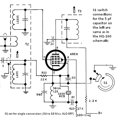
The .01 µF capacitor on the oscillator plate (pin 6) represents a 4.5 ohm resistor to ground for AC (RF), this means a short circuit to ground. The 6BE6 converter tube works as an IF amplifier on single conversion ranges, and as a true converter on double conversion ranges.
L26, which was located on the 6BE6 plate as a wave trap for 3490 Kcs is now placed on the cathode to block that frequency, thus preventing the cathode from being shorted to ground. That L/C combination must have enough inductive reactance at the resonant frequency and a very low DC resistance. If cathode bias is required, a suitable resistor shunted by a capacitor of about 0.01 µF should be included between pin 2 and the junction of L26 to the 560 pF capacitor. R13 is the resistor (its value also determines XLO bias) that connects the 6BE6 control grid to ground via L455, and to the input signal via two 5 pF capacitors in series. All of this represents an input of high-impedance (pin 1), thus creating a high-Q coupling. Cathode is connected to ground by S1, therefore the XLO is disconnected. With this configuration 6BE6 works as a pentode tube similar to 6BA6 (**). The 20 pF capacitor of the Colpitts voltage divider represents a high capacitive reactance at 3490 Kcs, therefore a high ground resistance value, it does not presuppose any damping. This is how this stage works on single conversion.
On double conversion S1 opens and the XLO starts working. At the same time the intermediate connection between the two 5 pF capacitors is connected to ground, thereby cancelling the 455 Kcs IF input on the 6BE6 grid that was working as a control grid (pin 1) and a 3035 Kcs IF input is activated on the mixing grid (pin 7), thereby giving a 455 Kcs heterodyned output on the 6BE6 plate (pin 5). The 10-18 Mcs and 18-31 Mcs connections at right of the switch wafer S1-GF in the double conversion schematic must be changed to be able to manage the 6BE6 cathode connection.
(**) When S1 is set from 0.54 to 10 Mcs, the 2nd conversion circuit should not operate as a converter but as an IF amplifier, and the intermediate tap of the 5 pF capacitors should not be connected to ground. Cathode of the 6BE6 tube is connected to ground by shunting L26 and the 560 pF capacitor; then the XLO will stop oscillating because its plate (pin 6) is also connected to ground. When S1 is set from 10 to 31 Mcs, these positions must be reversed: the 6BE6 cathode must be disconnected from ground and the center tap of the 5 pF capacitors must be connected to ground. The connection of the S1-GF switching wafer to the center tap of the two 5 pF capacitors in series is the same as in the HQ-160 schematic, but the other connections of this switching wafer must be changed to connect the cathode as shown in the schematic above.
|
— Leaving aside the important issue of spurious frequencies, the HQ-160's performance can be clearly classified as very good. Dial accuracy is very good (without using the calibrator), and excellent when a frequency range is set to a multiple mark of 100 Kcs with the calibrator (after the location may be fixed with the moveable hairline). IMO this is due HQ-160 has the same RF/mixer/LO coils of HQ-150 (classic-style design). Very good sensitivity in all ranges, and good signal-to-noise ratio behavior (especially when using the Q multiplier that adds selectivity and bandpass narrowing), gradual smooth pitch change on SSB and CW using BANDSPREAD tuning when the CW PITCH control is located from 2 to 3 divisions off center, very good audio, and surprising stability after a short warm-up time.
IMHO, the electronic design of this receiver (or others of very similar design) is the absolute minimum design that a tube receiver must have for modern use, understanding "modern use" as use on communications, not on listening commercial AM stations (this can be done by any receiver, no communications receiver is needed). This receiver admits modifications without the rest of the circuit "shed tears" because of it (as it does on the HQ-145). All lower designs than this are for listening AM, learning, collecting, or decorating a Ham-Shack. Distribution of components on the chassis is quite flat, this allows modifications to be made easily, therefore it is a very good candidate to be customized to personal taste without having to make great efforts that may affect the original design.
|