|
Scope: SSB reception with AGC enabled on AM-type receivers.
AM/SSB differences and problems
| Signal |
Feature |
Detection base |
Issue |
Solution |
AGC circuit |
Issue |
Solution |
| AM |
Fixed RF (carrier) + sideband RF when amplitude modulated. |
Carrier as a reference 'to extract' audio from a sideband. |
- |
- |
Uses carrier and sideband power to generate AGC voltage (a). |
- |
- |
| SSB |
RF only when there is sideband amplitude modulation. |
No. Missing carrier. |
Signal NOT intelligible. |
BFO, high-output to generate carrier-emulating RF for audio 'extraction'. |
There is only sideband energy. |
Some lack of AGC for audio control. S-Meter will indicate weaker signal than the actual. |
Increase AGC voltage generated by the sideband to the virtual sum SSB modulation + an 'AM carrier' (b). |
| AM to SSB problems |
Signal detection |
Signal control |
| Therefore, just as an SSB signal needs some "carrier" level to be demodulated, it ALSO needs some "carrier" level to be handled. |
• The HQ-160 model has a built-in product detector, but a product detector is not essential to solve these two problems, it only helps. The essential things are a BFO with good output level and a long IF chain under AGC. A product detector is simply a mixer, when it exists the signals "mix", when it is missing the signals "beat" (c). The only advantage is that the mixing procedure allows for better signal processing and a BFO with lower output can be used. The HQ-160 has signal detection well solved by design, what is missing to complete and modernize SSB reception is signal control. The classic AGC circuit, such as that of the HQ-160, is designed to process AM signals. These AGC circuits, when processing SSB signals, "perceive" the signals are weaker than they really are due to the absence of the carrier (d). Enabling only the AGC on SSB (e) does not completely solve the problem since the AGC voltages generated by AM signals and SSB signals are different (f). At the time the HQ-160 was designed the standard procedure in mid-level receivers was to receive SSB with AGC disabled, CW-style (g).
(a) There is a misconception that AGC voltage is extracted solely from the audio energy. This is not true, and is easily verifiable by tuning an unmodulated carrier or calibration frequency; S-Meter will show the RF level of the unmodulated signal.
(b) For an AGC designed for AM to work well in SSB, the average value of the AGC voltage in the circuit should be the same as for AM and SSB signals of the same audio level. These AM/SSB AGC level issues are automatically resolved with the audio-AGC design.
(c) A "beat" detector is also good for SSB; in fact, a BFO that injects signal into a diode is also a "product detector" since a diode can, passively, work as "a mixer".
(d) This partially disables the normal effect of an AGC when a receiver is modified or used to receive SSB with AGC enabled, AM/SSB level equalization is still missing.
(e) See 'Signal control-1' below.
(f) To completely solve the problem, approaches like the one shown in the 'Signal control-2' below are needed.
(g) Perhaps this is the reason why HQ-160 did not have SSB operation with AGC enabled. As demonstrated below, this model makes possible to include AGC SSB-ON without increasing manufacturing costs too much and without side effects (the original performance is not weakened and the original appearance is respected). |
Foreword
Adding a product detector to receive SSB with AGC enabled is discussed in detail on the HQ-145 page (click to Home→ES_list ). The HQ-145 has no product detector, it is simply a basic receiver with extras; the HQ-160 is a much more well designed receiver. Adding a product detector with AGC enabled in the HQ-145 receiver along with the imposition of leaving the front panel in original condition (modifying the front panel of old equipment should always be avoided or seriously considered) implies an exclusive design that gave me a lot of work, a time consuming experience, but the HQ-160 is a much more complete radio, it has a product detector with separate AM/SSB circuits, this make things easier. The HQ-160 combines old Hammarlund designs with new ones; the classic Phasing control is replaced by a Q Multiplier control (SELECTIVITY) which has the advantage of boosting signal and reducing bandpass simultaneously (thus, insertion loss is automatically compensated). ). The HQ-145 has no product detector, it is simply a basic receiver with extras; the HQ-160 is a much more well designed receiver. Adding a product detector with AGC enabled in the HQ-145 receiver along with the imposition of leaving the front panel in original condition (modifying the front panel of old equipment should always be avoided or seriously considered) implies an exclusive design that gave me a lot of work, a time consuming experience, but the HQ-160 is a much more complete radio, it has a product detector with separate AM/SSB circuits, this make things easier. The HQ-160 combines old Hammarlund designs with new ones; the classic Phasing control is replaced by a Q Multiplier control (SELECTIVITY) which has the advantage of boosting signal and reducing bandpass simultaneously (thus, insertion loss is automatically compensated).
This mod does not enhance one area of performance at the expense of performance in another area as often happens
on Ham mods. The modification described below is easy and effective, not only for SSB reception but also on AM. Adding an AGC stage to the IF chain improves a lot the performance of this receiver, both on AM and SSB. A radio with only two AGC stages (1 RF + 1 IF) has a lot of dynamic range, but this is a design for receiving commercial broadcasting on medium wave, not shortwave communications. Dynamic range is not good for SSB, that's why true SSB receivers have limited dynamic range. For handling SSB comfortably (which means AGC enabled), a receiver must have at least 3 IF stages under AGC, so even with this mod (1 RF + 2 IF), one is still missing!
Adding S-Meter operation with AGC enabled improves SSB reception, but the control of an AM type AGC over the incoming signal is still not enough, the SSB signal should be AM-equivalent in AGC voltage. To completely solve the problem of an SSB signal being under full control of the AGC of an AM type receiver (see table above), it is necessary to equalize the AGC voltages on both AM and SSB. This update has been on hold for some time, but you can now check it out in the 'Signal control-2' section below.
Original design
- Fast AGC voltage is provided by the pin 3 of the Z2 "chip".
- Delayed AGC voltage is provided by the pin 6 of the Z3 "chip".
- V5 grid is connected to AGC line.
- Variable voltage for the S-Meter is provided by the cathode of V5 when grid voltage varies,
this also causes cathode voltage variation.
- V6 grid is not connected to AGC line.
- V5 and V6 cathodes are submitted to the Sensitivity control.
- Fixed (reference) voltage for the S-Meter is provided by the cathode of V6.
- The adjustable point in the cathode resistor of V6 (ZERO adjust) adjusts equal voltage in both cathodes
at no signal.
- When both cathodes are equal in voltage S-Meter = 0.
- S-Meter is disconnected on MAN & CW/SSB.
- AGC voltage is connected to chassis on MAN & CW/SSB.
- The S-Meter sensitivity is controlled by a variable resistor that causes shunt resistance.
- S-Meter is 0-1 mA instrument, 60 mV end scale.
Wire identification list
- Brown: Sensitivity control line.
- Yellow/Black: V6 cathode central pin of the S-Meter zero adjustable resistor.
- Yellow: One end of S-Meter sensitivity adjustable resistor.
- Green: Pin 6 o the Z3 "chip", delayed AGC output line.
- Green/White: Pin 3 o the Z2 "chip", fast AGC output line.
- Red/Black: B+ receiver line.
- Red/White: B+ PD/BFO line.
- Red/Green: AF input.
- Yellow (shielded): Pin 4 o the Z2 "integrated circuit", AM Detector output line (*).
- Green (shielded): Product Detector output line (*).
The Mod: Parts list (Signal control-1, using the HQ-160's standard AGC bias source for both AM and SSB).
- 1-lug strip.
- 1 Mohm resistor.
- 56 Kohm resistor.
- 560 ohm resistor (replaces 1 Kohm R26).
- .010 µF capacitor (10 KpF).
- .470 µF capacitor (slow AGC).
- A BBM (* non-shorting) 3-position, 5-pole switch (as minimum, it replaces the original S6 FUNCTION switch).
Additional parts list (Signal control-2, adding a specific AGC bias source for SSB).
- Red/Black-Red dual wire (speaker type, thin, 1 meter or 3').
- 13 terminal strip circuit (SSB AGC bias, see pic below).
- 4.7 pF capacitor (input, P, V6 plate).
- .1 µF capacitors (8).
- Ge diodes, detector type (8).
- 100 Kohm resistor (output, C, FUNCTION switch).
- 4.7 Mohm resistor (slow AGC on signal peaks, see text).
- 1.8 µF capacitor (slow AGC on signal peaks, see text, replaces .470 µF).
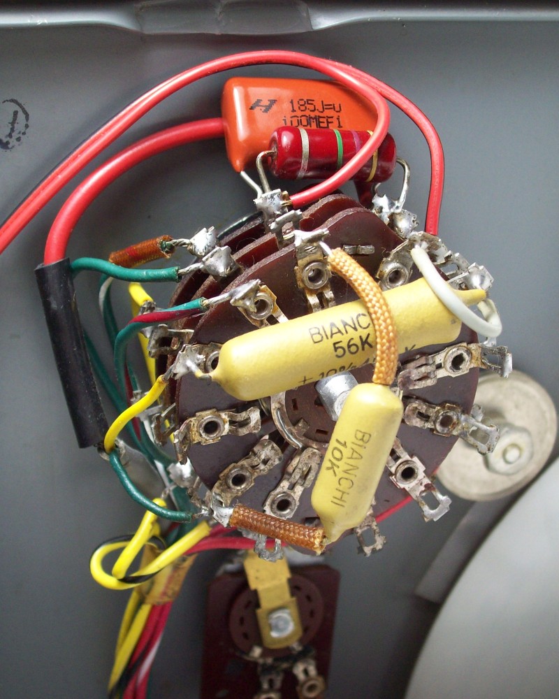
(*) If a MBB (shorting) switch is used, it is mandatory to install a coupling capacitor for each wire of the shielded cable (green and yellow). They should be located on the switch position lugs, deleting the one on the pole lug. A different value can be chosen for each audio line, for example, the existing 10 KpF capacitor for the green wire (SSB) and a new 56 KpF capacitor for the yellow wire (AM), see pic at bottom.
Switching contact designs:
BBM (Break-Before-Make): Opens the first set of contacts before engaging (closing) new contacts. For a short period of time, the switched path is an open circuit.
MBB (Make-Before-Break): The current connection path is connecting before the previous path is completely disconnected. The switched path is never an open circuit.
Enabling AGC on SSB/CW: S-Meter and AGC operation on SSB in the Hammarlund HQ-160.Signal control-1.
The goal of this mod is to enable AGC on SSB and lengthen the IF chain under AGC (see table on top). Steps are:
- The S-meter is disconnected from its current variable voltage source (cathode of V5).
- A new variable voltage source is established (cathode of V6). This IF stage is released from the Sensitivity control and included in the AGC line for best SSB signal handling. Now V6 has variable voltage in its cathode that depends on the strength of the signal, this makes up the variable voltage source needed for the S-Meter.
- A new fixed voltage source to the S-meter is created by means of a divider
network from the 0B2 stabilized line. With this, the original fixed voltage source to the
S-Meter from the cathode of V6 is replaced by a fixed voltage source extracted from the
voltage regulated line. Current S-Meter connections (+/-) need to be reversed.
- It is necessary to modify the operation of the FUNCTION switch, a 5-pole, 3-position switch is needed. Now AGC is off only in the MAN position of the FUNCTION switch. An increased AGC time constant is selected on SSB.
In order to adapt S-Meter operation to the new circuit, the popular and reliable single tube S-Meter design has been adopted, thus combining AGC control with S-Meter operation in a single stage. The variable cathode voltage is compared with the fixed voltage provided by a voltage divider associated with the screen's fixed voltage source (due to the action of the VR tube). The S-Meter bridge values have been precisely arranged; if there is tube failure, or there is no tube, the S-Meter needle only goes to the end of the scale, never beyond, so the meter is fully protected. These S-Meters require a 60 mV DC potential difference between the polarized terminals to reach the full scale mark, thus passing 1 mA through the winding, then the internal resistance of the meter is 60 ohms. A 56 Kohm resistor and a 560 ohm resistor connected to the regulated 105 VDC line make up a 1 volt voltage divider on the positive side of the meter. The 390 ohm resistor in parallel with R28 halves its value providing fine adjustment to zero adjust, and when the S-Meter is set to zero with zero signal (SENSITIVITY fully counter-clockwise), this S-Meter network provides an effective V6 cathode resistance of 70 ohms, which is the correct value for a 6BA6 tube (receiver OFF, the total cold ohmic value measured at the cathode of V6 is about 70 ohms, the standard 6BA6 cathode resistor value is 68 ohms). All this means that V6 will operate with standard amplification values, this increases the sensitivity of the HQ-160 (the IF chain has a lot to do with the sensitivity of a superheterodyne), but this signal increase is almost at the limit of the input value of the product detector, one could consider reducing the value of the coupling capacitor to the product detector (C5). The voltage at the cathode drops considerably with an incoming signal, the voltage at the divider almost does not change (screen grids of the IF tubes are voltage regulated), therefore the voltage at the cathode is less positive, this means the meter will rotate clockwise depending on the incoming signal strength.
No new cable lines are needed at this stage of modification. This mod includes slow AGC on SSB position, this is accomplished by a .470 µF capacitor located between the switch lug that carries the fast AGC line and the chassis. The fast attack is accomplished with the aid of a drawback that in practice becomes an advantage: There is a small leak of BFO signal through T8 to the AGC line, the S-Meter evidences this, it takes an advanced minimum position (around S2/S3). This BFO-AC leak is rectified and causes the AGC line remains polarized (biased), this equalizes(1) the usual AM/SSB performance difference via AGC. The best advantage of this "drawback" is that when a sudden input is present, the rise time, AGC attack(2), never is located at the lowest starting point(4), in fact, it is already located a bit up the response slope of the AGC circuit. The "drawback" gives solution to two of the three technical aspects that must be always solved on SSB signal acceptance; fast attack, AM/SSB signal level balance, and the third, slow release(3), which is performed by the .470 µF capacitor. An increased/decreased value of this capacitor will add more/less time to the slow AGC release. Adding capacitance value is only necessary when syllabic vocalization is affected when receiving very strong signals; a capacitance value of .470 µF (470 KpF) covers these cases.
(1) AM/SSB audio level balance: Typically achieved by weak SSB signal coupling to the input of the product detector.
(2) Attack time: Amount of time delay between the instant reception of a strong signal and the pulse of AGC voltage that reduces gain.
(3) Release time: Time lag between the disappearance of a strong signal and the moment when the AGC voltage returns to its average value.
(4) The Collins 75A-4 receiver uses the same method but, instead of getting an extra fixed bias automatically, gets an extra variable bias manually. Collins biases the starting point of the AGC slope positioning the RF gain control slightly advanced (this increases negative voltage to the AGC line), thus lowering input signal strength and increasing AGC attack. Copying here below from the 75A-4 manual: "Operation - Tuning SSB signals d. Readjust the RF gain control until the S meter kicks up not to exceed three S points or 20 dB with the voice modulation. If the S meter kicks much more than this with the modulation, a popping or pumping effect will be observed due to the necessary attack time of the AVC".
Mouse Over/Out to compare modified circuit vs original
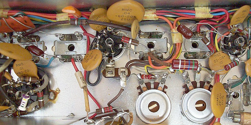
The wiring of the mod: Adding AGC to another IF stage and S-Meter operation on SSB.
 A refurbished IF transformer from SMD issue just above; detailed info on the Silver Mica Disease page.
AM/SSB signal equalization: Balancing AGC AM/SSB voltage for similar audio level signals.Signal control-2.
Classic AGC circuits, like the one in the HQ-160, were not designed to receive SSB signals, they always assume are receiving AM, so AM AGC circuits are not fully effective when receiving SSB (see table at top). This second part of SSB signal processing in circuits designed for AM is always forgotten, simply patched by assigning high time constants to the AM AGC system. On dedicated AGC circuits for SSB, to avoid the problems of high time constants, it is mandatory to lower them, and compensate for the decrease with an AGC-controlled IF chain as long as possible (equivalent to "ironing" the SSB signal).
This additional job completes the modification, and is carried out taking into account that an AM-AGC reacts differently to SSB signals than to AM signals, not only in time constant but also in level. If this last consideration is not taken into account, the AM-AGC circuit "thinks" SSB signals are weaker than they really are due to the absence of the carrier voltage. It is not enough to implement a procedure to operate SSB AGC-ON, some AGC signal level conversion must also be performed.
Therefore, some 'carrier voltage' must be provided to the AGC circuit along with the voltage that corresponds to the SSB signal, making it work like with AM signals; all other options work as a patch. The compelling alternatives are the audio-AGC design or an AGC circuit designed specifically for SSB. The differences of this second part with the first one above are:
- A specific AGC signal level source is added (see below). Its inclusion eliminates the effect of the S-Meter never reaching zero with BFO-ON even when the sensitivity control is set to minimum (see signal control-1, BFO leakage into the AGC line).
- The signal pickup for the SSB AGC source is made in the V6 plate, a distant and independent location from the AM-AGC and BFO-PD circuits. The AGC base voltage is no longer a remanent voltage caused by BFO leakage, but a controlled voltage that is equivalent to the virtual existence of a carrier (a procedure equivalent to that performed in the product detector).
Making the HQ-160's AM AGC compatible with SSB signals: There may be several strategies to achieve this, the one used here is based on adding "carrier units" depending on SSB signal strength into the AM AGC system. This design is based on the fact that for an SSB signal to be processed correctly with an AM-AGC circuit, in addition to include the voltage generated by the SSB signal (audio level) into the AGC line, it is also necessary to add an equivalent "carrier voltage" to make it "AM compatible".
- To do this, some IF SSB signal (with the background noise from the modulation gaps) is extracted from the V6 plate, avoiding loading the V6/T7 stage by means of a capacitor of only 4.7 pF, this represents a load to the IF of 75,000 ohms, a high value that prevents the Q of the circuit from being affected, but of course, it adds some parallel capacity, so a slight readjustment of T7 is necessary.
- Next, the small RF voltage extracted is octupled (8x) with the intention of obtaining an output voltage that represents doubling, ±2x with load, the voltage produced at the AGC output for AM. The octupler is made up of 4 stacked half-wave doublers (to some extent, this circuit is equivalent to an AGC amplifier).
- A 100 KΩ smoothing resistor followed by a high time constant filter (4.7MΩ of R and 1.8µF of C) that is effective only on signal peaks provides the "carrier voltage" needed for the AGC circuit to operate on SSB so very similar to how it performs on AM. The S-Meter needle will show this "carrier" voltage + the voltage generated by the sideband audio in a similar way as in AM it shows carrier level + modulation peaks.
- FUNCTION switch disconnects the AM AGC voltage source and connects this SSB AGC voltage source.
There are now two AGC voltage sources: one for AM (AVC position) and one for SSB (CW-SSB position), which are selected with the FUNCTION switch. Simple and effective, see below.
Full mod including separate AM and SSB AGC voltage sources. Mouse Over/Out to compare with 'Signal control-1'.
AGC special bias source for SSB: Very low coupling (4.7 pF) compensated by high voltage output (octupled).
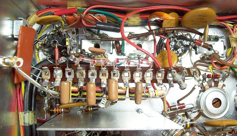 An end-of-IF-chain terminal is added for alignment (X, T8 green dot lug). A VTVM demodulator probe type Heathkit 309C is required.
Current MBB FUNCTION switch with capacitors for AM audio (56K), SSB audio (10K), and the RC time constant for SSB peaks.
Final features: (Signal control-1 + Signal control-2)
- — Unlike current "s-meters" in SSB rigs (that in fact they work like VU-Meters, volume indicators not Strength indicators), the HQ-160 S-Meter will show a combined value of the SSB signal + the virtual carrier level depending on the SENSITIVITY control setting (AM style, not with VU-Meter motion-style), whose reliability in 'S' will depend on the degree of coincidence of the "carrier" level with the signal level. A particularity on this regard is that in the absence of signals, or with weak signals, the S-Meter will only show the sensitivity level the receiver is set to; the 'S' values begin when the needle shakes or shifts due to modulation peaks.
- — A clear advantage of this design is that the annoying effect called "moment of silence", common in HQ-170/180 and R-390A receivers, which is produced by switching out effect or by receiving a sudden pulse of noise, is non-existent. This is because the added "carrier" bias voltage, that is proportional to the SSB signal and the background noise, is what controls the behavior of the AGC line, not the voltage stored in a capacitor at high time constant. The amperage capacity of a voltage multiplier line weakens as multiplication cells increase, this is equivalent to a bias source with variable internal resistance depending on the load, thus the internal resistance of the SSB AGC source follows the voltage level it delivers, therefore the high time constant RC network has influence in the circuit only when AGC voltage is maximum. The 8' high time constant filter added to the AGC bias source controls only the modulation peaks above the "carrier" voltage, not the entire signal level path (AM envelope style, 4.7MΩ of R is a signal peak setting value, its average operating influence is much lower), therefore all this fits perfectly into an AGC line designed for AM signals.
- — This design makes the SSB's popular AGC attack and release time values almost obsolete, since the SSB signal is always "tied" by the AGC (the automotive simile would be driving a car selecting low gear). This is because when the SSB signal is missing in a modulation sequence gap, the virtual carrier is always there. The AGC attack and release times are only effective at strong signal peaks, and are adjusted based on the level of the inserted virtual carrier. The virtual carrier level as a function of the noise processed by the receiver is the only adjustment required by the system. Signal and noise levels are related, the virtual carrier level is mainly generated by the background noise, and signal and noise depend on the adjusted sensitivity level of the receiver. All this are the keys to the entire system.
- — SSB demodulation quality is excellent, there is no any "pop" at the beginning of the transmission, nor sporadic syllabic "pops" under very strong signals. This AGC mod makes the product detector to work 100% perfect, no need to touch it up.
- — Delayed AGC always works in "AM style", but the influence of the delayed AGC on SSB performance is marginal since it only acts on the input RF stage. When receiving SSB with AGC enabled, the most important IF steps are those before the product detector. This arrangement also allows the input RF stage to not be controlled by a "doped" AGC and therefore act inappropriately on weak signals.
- — On AM, the AGC works according to the original receiver design + the inline IF stage (V6) added by 'Signal control-1'.
- — Full HQ-160 schematic on 3 pages including the mods.
A next improvement that could be implemented in this receiver may be a noise limiter that, in addition to working on AM, as the current one does, also does it on SSB. Communication devices that can be repaired or modified with relative ease could be classified, IMHO, as 'true Ham-devices', the Hammarlund HQ-160 is one of them, this makes the difference between customizable-type communication devices for electronics hobbyists and appliance-type communication devices for recreational use.
Adjusting the Q multiplier and the BFO alike
Now the S-Meter works on SSB, this permits to use its readings
in order to perform accurate Q multiplier and BFO alignments.
Wait for 30 minutes of warm-up time.
- 1) Selectivity OFF, Function AVC, Calibrator ON.
- 2) Tune CAL signal with Antenna and Bandspread to maximum S-Meter deflection, set S-Meter to S5 with Sensitivity.
- 5) Function to CW-SSB (BFO ON).
- 6) Tune CW PITCH (BFO) to zero beat, note knob position.
- 3) Selectivity ON, knob 2/3 advanced.
- 4) Tune FREQ (Q multiplier) to maximun S-Meter deflection, note knob position.
- 7) Calibrator OFF.
- 8) Loose FREQ and CW PITCH knobs, centering both at arrow markings.
- 9) Adjust knob endpoints loosing respective ring-stops that are in rear of the panel.
|


