|
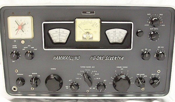
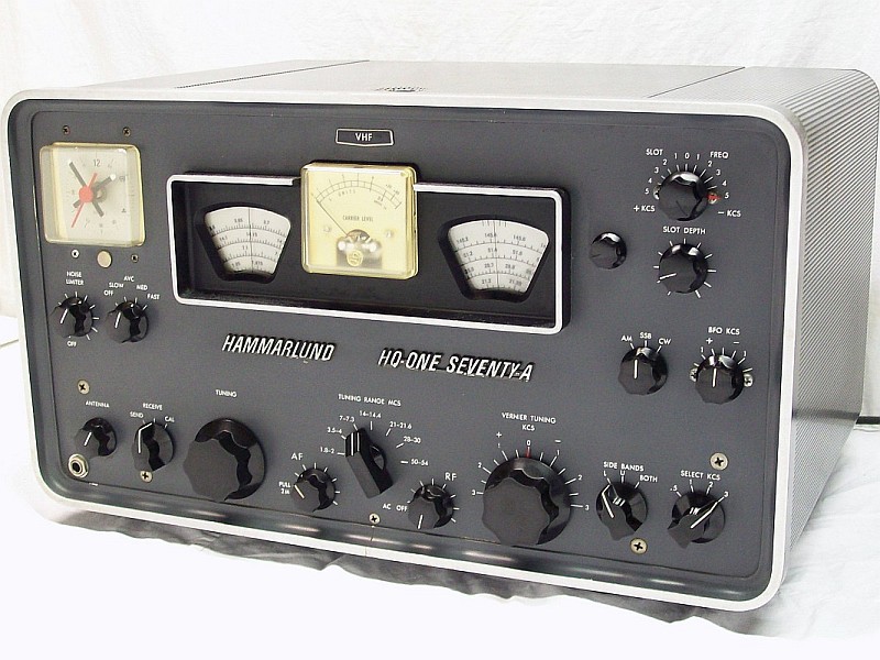
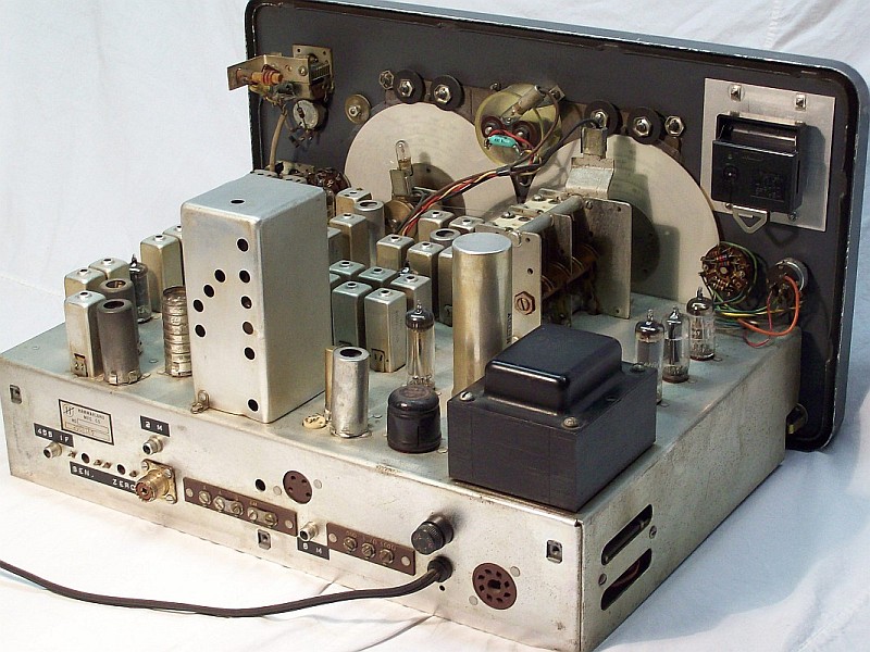
Introduced in 1958, it is the Hammarlund's top model for Ham bands reception. With same dimensions of his 'big brother', the model HQ-180, it also shares circuitry layout, the HQ-170 (17 tubes) covers amateur bands of 160, 80, 40, 20, 15, 10, 6 meters of wavelength. The HQ-170 issue #1 has an interesting peculiarity not found on rest of models: the local oscillator circuit is a Hartley type oscillator, all rest of models have a Colpitts type oscillator (begining with issue 2).
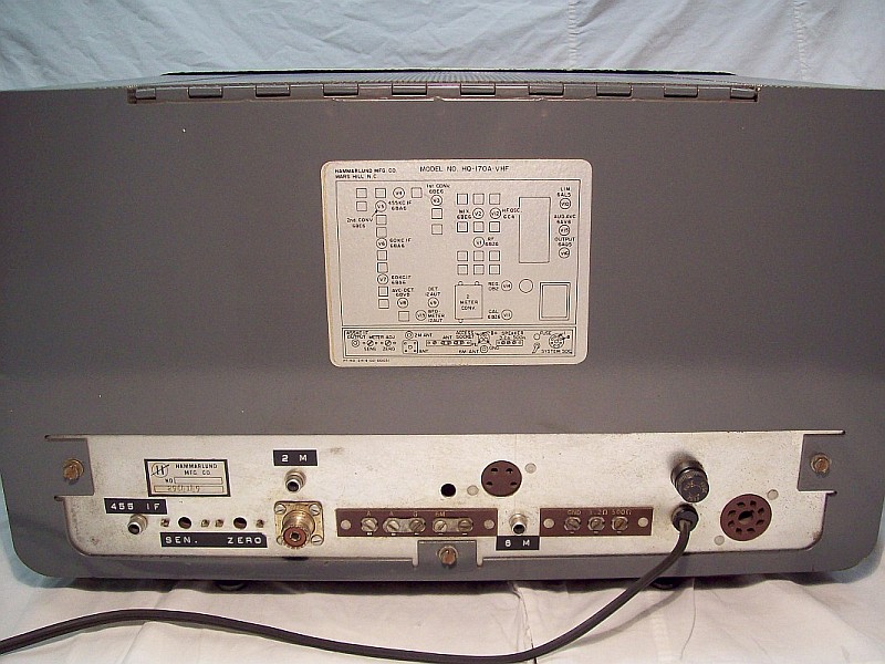
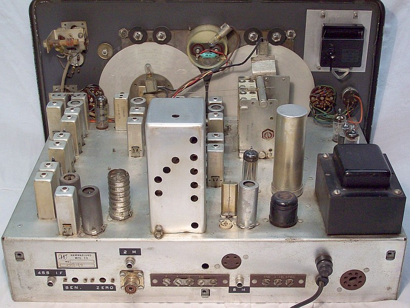
In 1963 the HQ-170A (16 tubes) replaces the standard HQ-170 with all the typical modifications issued for A models (see below). Finally, in 1964 the VHF version (20 tubes) incorporates a 2 meter converter with 4 nuvistor tubes that can be selected by pulling the volume potentiometer out with the band switch pointing the 6 meter band, thus it is clear that this VHF converter has an IF output within the 6 meter band, this IF amplifier is used as RF amplifier when the 6 meter band is selected. This converter adds an extra antenna RF stage for the 6 meter band, in addition to including the 2 meter band, resulting a quadruple conversion receiver: double in the 160 and 80 meter bands, triple in 40, 20, 15, 10 and 6 meters, and quadruple in the 2 meter band. The 2 meter converter generates a design of four intermediate frequencies (1st FI at 52 Mcs, 2nd FI at 3035 Kcs, 3rd FI at 455 Kcs, 4th at 60 Kcs), the 1st FI is only generated when the 2 meter band is used and its 52 Mcs radio
frequency amplifier is added to the RF input antenna step in the 6 meter band.
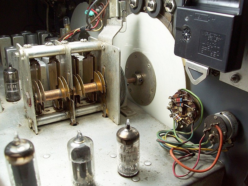
Model non A has a 3-section tandem capacitor (RF amplifier + Mixer + LO sections), and model A has a 2-section tandem capacitor. Since the RF section in the tandem is removed, the RF amplifier is fully tuned by the ANTENNA trimmer. In any receiver, the ANTENNA trimmer should always be readjusted even if there is synchro-tuning between steps (RF/ Mixer). Since the HQ-170 is only for amateur radio bands, this suppression can be considered correct because the frequency range for each band are not wide, therefore the capacity value of the ANTENNA trimmer can easily tune and adjust any frequency of each band.
The first converter (second with VHF converter in-circuit) is of the combined type, that is, it acts as an IF amplifier on double conversion bands (triple conversion with the VHF converter) or as a Xtal converter on triple conversion (quadruple with the VHF converter). This step is associated to a switch that deactivates the local oscillator (OL) and, or converts the step into an intermediate frequency amplifier (FI) by mass decoupling the dual
shielding grid that acts as an OL plate, or converts the step in the
mixer when eliminating this decoupling and deriving the grid input 1 to
ground that gives way to the intermediate frequency from the previous
conversion. The 3rd conversion mixer (4rd with the VHF converter) is
composed by a mixer that provides an output of 60 Kc and a variable
local oscillator in a range of only 6 Kcs that constitutes the so-called VERNIER
TUNING, which is in fact a passband tuning, a sideband fine tuning device especially dedicated to SSB reception.
On double conversion ranges (triple with the VHF converter) the first mixer directly generates
a 455 Kcs IF, and on triple conversion ranges (quadruple with the VHF converter) generates
a 3035 Kcs IF, which is injected into a converter that generates the 455 Kcs IF.
On both cases this IF is injected into the last mixer that generates the 3rd
IF (4rd with the VHF converter) of 60 Kcs. The LO of this last mixer can be adjusted ± 3 Kcs on
panel. Precisely is in this IF chain (60 Kcs) where resides the sideband tuning system
and the selectivity circuitry, followed by the demodulation stage, containing a product detector with a Clapp-type BFO, the detected signal may be processed by an adjustable noise limiter. Using the VHF version the first mixer cited above tunes signals provided by the 2 meter converter, that generates an output of 52 Mcs, that's why the 6 meter band must be selected to receive the 2 meter band. This converter permits to use its 52 Mcs IF amplifier stage as an added RF stage in front the standard antenna amplifier when the 6 meter band is selected.
To aid on interfering signals a slot filter covers the whole 455 Kcs IF output channel (± 5 Kcs), and whose frequency and depth can be adjusted on the front panel, but, as is usual in this circuits, it is very effective for carrier interference (or CW), but much less effective for modulated signals.
The Hammarlund's SSB system must be operated in reverse of the usual, that is: BFO must always remain adjusted at center of the IF passband, NOT placing the "BFO carrier" aside, and the incoming sideband must be tuned by the corresponding sideband circuit; so to tune a lower side band the vernier must move about 1,500 Kcs to the left (+fr), and for the upper side band the same to the right (-fr), this is the VERNIER TUNING knob function. Is in this conversion stage (60 Kcs) where reside the sideband separation/selectivity circuits, followed by a product detector circuit with the BFO, the detected output can be connected to an adjustable noise limiter. The HQ-170/180 SSB circuits are identical to the Hammarlund HC-10 converter circuits.
The performance of this receiver can be classified as excellent on signal-to-noise ratio; and on sensitivity, excellent for the 160, 80, 40, 20 meter bands. and very good for the 15, 10 meter bands. Very good selectable selectivity steps, easy tuning on SSB either by sideband selection or without selecting sidebands, good audio, and remarkable stability after a short warm-up time that depends on selected band (at higher frequencies more warm-up time is required). As usual on pure Armstrong-type receivers (LO in 1st converter/mixer stage) some drift may exist, especially on higher bands. About this and making comparisons: the advantage of using low frequency conversion and tuning (e.g. Collins) is that the LO oscillates at a much lower frequency, this automatically makes it much more stable. The stability of the Collins receivers is not due to a magic wand, but the drawback of this low frequency heterodyne tuning system is that it implies the number of selectable tuning bands is greatly increased, this leads into a more complicate and expensive design.
Modes & Operating Procedures
→ AM
- 1) Function switch to "AM", AVC to "FAST", VERNIER TUNING to "0", SIDE BANDS to "BOTH", and SELECT KCS to "3",
NOISE LIMITER "OFF". Important! SLOT FREQ standard position is "+ 5 KCS" or "- 5 KCS", NOT "0".
- 2) Tune signal until maximum S-Meter indication is achieved.
|
→ FM (voice-range ONLY)
- 1) SIDE BANDS at "L" or "U", the rest as above.
Test best sideband because frequency response skirts are not symmetrical.
- 2) Slowly tune signal to achieve the best reception.
|
→ SSB
- 1) Start with AVC to
"MED", switch to "CW/SSB" and set BFO KCS at center (HQ-170),
select SSB (HQ-170A), VERNIER TUNING to +/- "1.5" depending on received
sideband, SIDE BANDS to "BOTH" and SELECT KCS to "3".
- 2) Tune signal until maximum
inteligibility is achieved, it is very easy if the received sideband is correct
and the SSB system is adjusted correctly. If the signal cannot become
inteligible change VERNIER TUNING to the opposite side (this occurs usually
on CB where does not exist a pre-defined sideband).
- 3) Switch SIDE BANDS to
"L" or "U" depending on sideband detected. Interference will be down and signal
will be up. Inverse selection causes signal disappearance (or almost, only
strong signals will be heard).
- 4) This is the fast and modern
procedure. Hammarlund describes a procedure using the S-meter and tweaking
continuously the VERNIER TUNING, it leads to go misadjusting the band centering,
these procedure is slow, outdated.
|
→ CW
- 1) Set AVC to "FAST", VERNIER TUNING to "0", SIDE
BANDS to "BOTH" and SELEC KCS to ".5" or "1", BFO KCS at center.
- 2) Switch to "CW/SSB" (HQ-170) or "SSB" (HQ-170A) to tune the
pulsating carrier at zero beat (S-Meter needle oscillates with no sound).
- 3) HQ-170: Adjust BFO KCS to desired
CW pitch. HQ-170A: Switch to CW, a CW pitch of 500 cs is automatically selected.
- 4) When the narrowest bandwidth is selected (".5") an interfering signal can be removed, but a loss of gain may be noticed.
- 5) SLOT FREQ accurately tuned combined with SLOT DEPTH at max can eliminate an adjacent carrier, but not an AM signal.
|
Model A features solid
state power supply and a separate always-connected filament transformer
that supplies voltage to the heaters of the high mixer tubes (V2 &
V12) in order to get more frequency stability and reduce initial warm-up
drift. These tubes runs 24/7, IMO it is a bizarre idea, especially when
Hammarlund says "this transformer also supplies the system socket"...
adding sporadic load to a line intended to improve stability usually
is not a good idea precisely. This model introduces individualized SSB and CW positions, BFO frequency is fixed
internally, it only can de adjusted acting on the BFO coil, thus the BFO
knob on panel does not work on SSB. The CW position in this model only
serves for obtain automatically the CW tone with BFO at center, but the
BFO control is operative on CW, may be adjusted and can left permanently
on the position desired in order to personalize the CW tone. On the rear
it has a called "system socket" that permits connecting additional gear,
also this model adds option of plugging to a 230 VAC power line. The HQ-170A was manufactured until
1967.
|