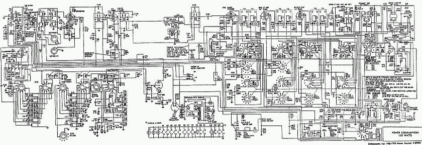
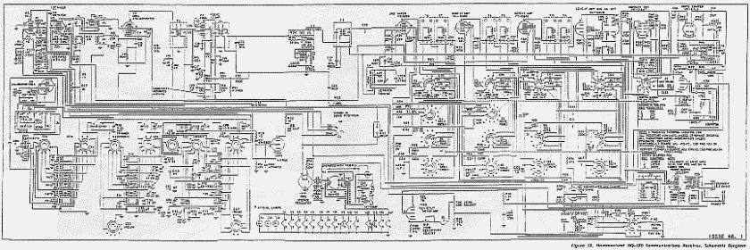
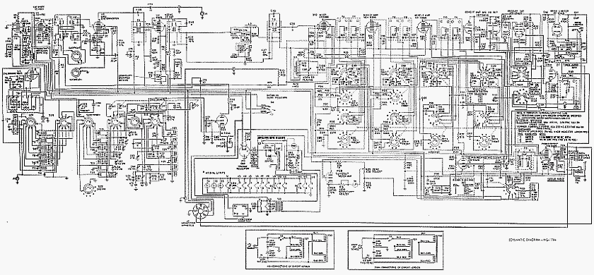
Info about this model 's capacitors.
There are NO waxed paper capacitors in this model, and the existing electrolytic filter capacitors are well sized and of good quality; thus if the electrolytics have not dried out due bad location in the chassis or sealing failure (rare), or have not become corrupted due to poor build quality (cheap mfg), THERE IS NO NEED TO REPLACE THEM. This model does not need the application of any "capacitor replacement kit", you would be spending money in vain. BTW, not all, but many of these kits take advantage of the CLICHE belief that the electrolytic capacitors always need to be replaced, this is simply not true, the cliche only holds true for waxed paper capacitors.
Electrolytic capacitors that have NOT experienced overvoltage or overheating are generally in very good condition, but are not YET usable due to depolarization, as it happens when newly manufactured (and before being polarized by the manufacturer). It is the user who damages the electrolytics when plugging in the device without taking into account this behavior, that is, the user causes the failure at that moment. There is no prior failure since depolarization is not a failure, it is a consequence of the elapsed time. It is disturbing to see that good vintage components go to waste because of a successful cliche, or for ignoring the risks associated with connecting a device that has been in storage for a long time. The consequence is that the original appearance of a device is compromised by totally unnecessary "repairs". I'm posting this warning because it's really disappointing that electronics hobbyists mistake normal behavior for a component failure (or cause the failure themselves).
When depolarized, an electrolytic capacitor is not a capacitor, it is a low-value resistor, but this does't mean mandatory replacement. The thing is: Just like a battery discharges over time, an electrolytic capacitor DEPOLARIZES over time; ALL electrolytics, old and new. This means that before reusing these capacitors after a long time in storage a polarization protocol must be performed. It basically consists of starting the device at reduced voltage, letting time pass, raising the voltage and repeating; a "rinse'n repeat process" until the capacitors no longer heat up. The prize is that it is possible to respect the original design without the need for additional spending, the drawback is that if the capacitor has not been used for many years the process can take many hours, but this should not be a problem for an amateur. See an example of the reforming process on the 75A-4's capacitors page.
About off-tolerance resistors: High impedance electronics, such as tube electronics, are usually very forgiving of component values. Barring large differences or values in critical circuits (e.g. bias), it will normally NOT be necessary to replace vintage resistors.
IMHO, the best advice that can be given about vintage equipment is: clean/repair it up just enough so that it does not look like scrap, but not enough for it to loose its history. On vintage equipment be conservative is mandatory, do not expect perfection nor seeking perfection.
An alignment should only be undertaken if there is a specific symptom that causes annoying issues (e.g. incorrect dial marking, evidence of loss of gain, etc.) and a repair should only be undertaken if there is an evident issue, or for to prevent a malfunction that will increase with use. Tubes generally last for decades and only the problematic tube should be replaced, a full tube replacement "by default" will cause misalignment, a good example is the LO tube: if it is replaced dial alignment will be needed. The same occurs with electrolytic capacitors, good quality ones last for many-many decades. The usual problem with old capacitors is with the soggy paper-type, but the grey HQ-line does not have these type of capacitors. RF switch wafers NEVER should be sprayed; spraying usually is not a correct procedure on electronics, use a cotton swab with cleaner and just wipe the contacts, so phenolic wafers can absorb the liquid sprayed, the wafer becomes resistive and changes its capacitance, this may cause leaks and frequency shift, specially on high bands. Same applies to porcelain wafers when dust mixes with the liquid sprayed.
Usually a top level vintage ham receiver like the HQ-170 does not need improvements, especially when it is already designed for SSB. Making mods in this type of receivers the only thing that is achieved is to improve a bit on something at the expense of losing original features, thus introducing new problems. BTW, if someone is planning a modification that needs a control located on panel, all Hammarlunds with a single SLOT DEPTH knob on panel (like HQ-170) are well suited to that. The SLOT DEPTH control may be removed because it remains adjusted at maximum rejection all the time. To do this, receiver ON: adjust max rejection using the CAL signal; receiver OFF: measure the global ohmic value of the series/parallel resistors; then replace this value with a fixed resistor, result will be similar to this one, or simply replace the potentiometer by an internal adjustable resistor.
Model HQ-170 has the VERNIER TUNING knob in a predominant position as if it were a fine tuning control for continuous use, this causes misunderstandings. Passband tunings and BFOs aren't clarifiers, normally they must be set in a fixed position depending on band selection and receiver's design, its adjustment must be in accordance with an accurate frequency reading on dial and a correct "decoding" of the received signal. In order to keep a receiver perfectly aligned, all tuning adjustments must be done with the MAIN tuning knob (or using band spreading). BFO and VERNIER TUNING are related to the IF step, not the RF step, tuning the input signal with these controls is inappropriate and will cause system mismatch. This unit was received with the SSB system bad configured, which is very common in Hammarlunds that have been passed through by several owners. It is very usual these two circuits have been misaligned due bad understanding of the system, but luckily most users don't dare to retouch the IF chain.
In order to make a precise adjustment of the sideband/bandwidth system, a good understanding of how this system works is mandatory, but Hammarlund does not aid for this on the manuals, sometimes on reading gives the feeling that neither Hammarlund knows exactly how the system works. What is assumed as normal is that the VERNIER TUNING knob must be set at center, and the BFO knob to one side depending on sideband, but in this system it is just the opposite. Once the correct setting has been established, these knobs do not need to be retouched (nor is it advisable), all subsequent tuning procedures must be done with the MAIN knob (if the SSB "decode operation" using the MAIN knob fails, the HQ-170's SSB system is misconfigured). In most SSB systems the BFO location "decodes" a receiving signal inside the whole IF bandpass; in this system the BFO also "decodes" of course, but the VERNIER TUNING selects the "decoding location" within the IF passband. With this, the SSB signal is located inside a "sandwich", pressed within the BFO "carrier" at IF center and the IF bandpass skirt, only using a half of the whole IF bandpass (an IF channel, the IF sideband); this configuration simulates a "mechanical filter effect".
An HQ-170 needs to have the SSB system very well adjusted, do not try to adjust it if you do not understand how it works, there are also errors and "lapses" in the manuals. It may be ridiculous to say, but it seems that Hammarlund didn't know exactly how his SSB system worked [Did the designer no longer work on the company? Was the design an external order?]. Helping not to make mistakes is one of the purposes of this pages. Since the Hammarlund's SSB system is unusual, many owners of these radios "adjust" it based on the more common SSB system, this makes it worse, and hence the usual complaint: Audio response.
BFO frequency at center must exactly match the "AM's heterodyned IF" of the receiver, this center should correspond with the heterodyne value of the previous mid-frequency mixer, whose output may not be the exact 455 Kcs value from the schematic, the centers of the SSB channels (USB/LSB) must exactly match the centers of the passband tuning sides, those are the keys. This "transfer of centers" is what makes the system critical. When an HQ-170 has "muddy" or "distorted audio" the audio stage is not usually guilty, what happens is the IF bandpass does not match with the bandpass of the adjustable passband tuning circuit (vernier tuning). By "improving" the audio section, the only thing that will be achieved is to add a wrongly configured stage in order to correct a wrongly adjusted stage. Also nor should we forget that the audio from a true communications receiver can never be as good as the audio from a home appliance, if it is, it is not a communications receiver.
About this, there is a typical modification of this receiver who has gone to solve the effect without analyzing the cause and, unfortunately, has become very popular: Deleting feedback in the audio stage. The Williamson-style audio feedback included in the audio stage (pompously called in the manuals "exclusive Hammarlund auto-response circuit") can never cause distortion, as it is precisely designed to eliminate distortion and compensate for the frequency response caused by the output transformer's response curve. This feedback circuit is initially aperiodic, the frequency correction is only determined by the frequency response of the output transformer depending on the power applied to the audio stage (the signal level applied to an output transformer affects its response curve, the Williamson circuit tries to correct this). If it is removed, it will simply produce a response that is predominantly midtone. Deleting feedback is interpreted as a solution to the distorted/muddy audio problem, but the source of the problem is not the audio stage, the source of the problem is bad SSB demodulation configuration, followed by user mishandling of some knobs. Hammarlund auto-response circuit") can never cause distortion, as it is precisely designed to eliminate distortion and compensate for the frequency response caused by the output transformer's response curve. This feedback circuit is initially aperiodic, the frequency correction is only determined by the frequency response of the output transformer depending on the power applied to the audio stage (the signal level applied to an output transformer affects its response curve, the Williamson circuit tries to correct this). If it is removed, it will simply produce a response that is predominantly midtone. Deleting feedback is interpreted as a solution to the distorted/muddy audio problem, but the source of the problem is not the audio stage, the source of the problem is bad SSB demodulation configuration, followed by user mishandling of some knobs.
The touch ups in this unit have been the following:
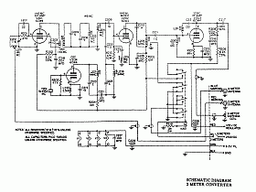
- Filaments of the first mixer and the oscillator tubes are now
connected when the power is on (like model non A).
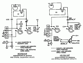
- A 10 pF capacitor was installed in parallel with the output coupling
capacitance (adjacent lugs, see schematic above) in order to provide more CAL signal on the 50-54 Mcs band.
This capacitance is in series with the 15 pF capacitor that is inside the
Z1 "integrated circuit", the actual capacitance of both (about 6 pF) is
the coupling output of the calibrator.
- The calibrator was unable to produce an exact 100 Kc signal due the standard Erie ceramic trimmer could not adjust oscillation due it was "frozen" (the rotating disk had become stuck to the ceramic base). It was replaced by an excellent Philips air concentric trimmer, a bit bulky, but IMHO the best trimmer ever designed. On using vintage radios, a calibrator is very important because it permits exact dial reading, in this manner a tube radio results competitive these days.
- One end of the L7 choke was, after 50+ years, securely welded to a chassis lug. The false contact caused S-Meter intermittencies.
- The oscillator coils of the 1st mixer were slightly retouched in order to get good dial accuracy.
- T28 (BFO KCS coil) was adjusted to match the exact IF value.
- L4 (the VERNIER TUNING oscillator coil) was adjusted to "0" at maximum IF mixing output.
- The pointer-type ANTENNA knob was replaced by a normal knob because this type has more precision to adjust.
This replacement is especially useful on 1.8-2 and 28-30 Mcs bands.
- In the panel hole for accessories there is installed a quartz clock instead of the usual Telechron clock.
The Hammarlund HQ-170 (A or A-VHF) is a great receiver for "hamming"(*) and to get used to using only the left hand for tuning, and that is precisely what you should not forget, it implies that VERNIER TUNING should not be used to tune or clarify the signal (if used in this manner, it must be repositioned correctly to perform a new tuning), it is to adjust the SSB system to the corresponding sideband even though the manual doesn't know it yet. Being in a dominant position, it is often mistaken for a signal tuning knob; bad 'positioning' of the BFO and misuse of this control is what causes all the audio and demodulation issues on SSB.
(*) "Vintage ham-radio operation", of course.
|


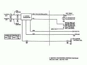
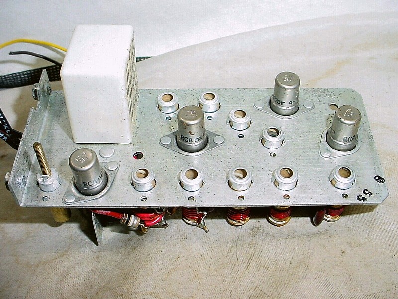
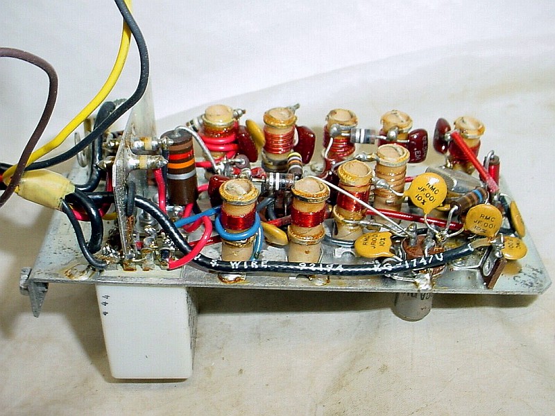
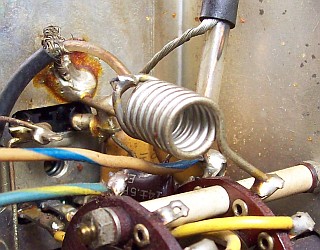 The converter-to-receiver coupling system in the 50-54 Mcs band.