A NOS Forway Industries TV-7D/U
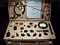
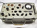
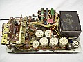
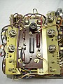
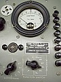
Below a totally original and little used TV-7D/U test set. Surprisingly and again, the nameplate
refers to model "B", but instrument and case refers correctly as model "D" and it has the exclusive range F on panel ... Forway's mfg
transition units from "B" to "D"?

All TV-7s: meaning of the controls on the panel and model-evaluation.
It is important to note that there is no definitive tube tester, neither analog nor digital, they all give only indicative results. What tube testers are really good at is taking snapshots of performance and comparing between tubes of the same type, that alone makes it worth having one. Any model from the TV-7 series will be a good candidate for that purpose.
In order to avoid confusions about the panel looks like, here is a special description:
- The FILAMENTS, GRID, PLATE, SCREEN, CATHODE, SUPPRESSOR switches are not voltage distributors,
are connection distributors.
- The voltage distributors are the BIAS control and the FILAMENT VOLTAGE switch.
- SHUNT is a control that is required only when the FUNCTION SWITCH is on
the RANGES A position, and adapts the maximum deflection of the meter to
the characteristics of the tube tested (diodes and rectifiers).
- The FUNCTION switch selects TYPE of test or LEVEL of test.
- The PUSHBUTTON selected starts the corresponding test.
- LINE ADJUST is a control that adapts the input line voltage to the set and determines
the internal voltages. This control seems marginal but is very important.
- The LINE TEST mark on the meter associated to the adjust of the LINE ADJUST control
should reflect the internal voltages are correct when LINE ADJ pushbutton
is depressed. Otherwise the tester may be "optimistic" or "pessimistic".
- The PLATE voltage applied to an amplifier tube is in most cases a fixed voltage of
about 150 VDC, but may be substituted by 56 VDC on low voltage tubes holding
down DIODE before depressing the MUT COND pushbutton.
- The SCREEN voltages are 130 VDC or 56 VDC, depending on tube characteristics, and
using the above same procedure for applying 56 VDC.
About appearances and models:
- It must be remembered that what works on a device is not the appearance but the content. Given certain limitations and issues of the TV-7 (some of which are described on these pages), it is interesting to note that a TV-7 often outperforms in price other, more efficient tube testers. This is probably due to the fact that the 'MIL look' of a TV-7 is impressive, not to the fact that it is better than the others.
- There are several TV-7 models, IMHO no need to obsess over model D. This model is only very useful for people who dare to adjust the device (precisely the intention of these pages is to provide info to help easily on that) since all the main adjustments are readily available. Model B also has all the adjustments available, there is an adjust that is only in model D, but model B doesn't need it (R139, bias to range F). Model D is the only one that has range F, but that range is useless since there are no tubes that test ONLY on that range, and those that ALSO test on that range are VERY FEW. Test'n adjust procedures shown here also apply to model B.
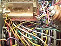
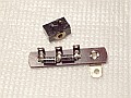
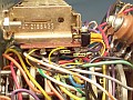
- Something that points in favor of the model D is that it has ferrite beads in almost all sockets to safely test high transconductance tubes like VHF/UHF TV converter tubes (e.g. 6DJ8-ECC88). It is unclear if they are absolutely necessary on a well-wired and operated TV-7, since the Gm test frequency is very low (50/60 cs). And it is also doubtful that these ferrite beads will make up the difference in price with model B (which BTW, also has ferrite beads on leads to pin 5 of UX6 and pin 2 of UX7)... let alone a standard TV-7.
- The high price of the model D is not due to its scarcity, as strangely enough it is the most abundant model. IMO it is due to the perception that the latest is the best. Simply saying that the differences between TV-7 models are few, and none to make a clear difference worth a notable price increase.
|
|
Mfg Specifications
| This instrument can perform the following tests... |
Dynamic Mutual Conductance and Gas (amplifier tubes), Emission (rectifier
tubes), Continuity (ballast tubes), Shorts, Noise, Panel Lamp test... it can also test Voltage Regulator tubes, but this test is definitely NOT recommended (TV-7 does a risky botched job
on VR tubes, more about this inside). |
| ... using these sockets... |
· American type 4, 5, 6, 7 pin tubes (UX4,
UX5, UX6, UX7 bases).
· Octal (IO - International Octal, A08,
K8A, MO - Mazda Octal, B08, M08 bases).
· Loctal (B8B, B8G, W8A bases).
· Noval (B9A base).
· Miniature (B7G base).
· Subminiature round (8 pin, B8D base) and
flat-type (7 pin).
· Acorn (7AA base). |
... and with these adapters...
(supplied) |
· E104
enables subminiature tubes with long leads to be tested in the OCTAL socket.
· E105
enables Septar
7BP base tubes types to be tested in the OCTAL socket.
· E107
enables 2C39 tube type to be tested in the OCTAL socket.
· Panel
lamps tester included in center of the UX7 base (FILAMENT switches positioned
on HR). |
| Indicator lights |
· PILOT, indicates "power ON", type 47 (6.3 volts, 150 mA,
incandescent).
· FUSE, indicates also a possible overload
condition, type 81, incandescent (6.5 Volts, 1.02 Amps, 6.63 Watts with
an effective resistance 6.37 ohms). It exists a popular replacement for
this bulb, a 12V-21W car bulb (12 Volts, 1.75 Amps, 21 Watts, 6.85 ohms);
this is NOT a bizarre replacement, the first design of this tube tester
(I-177) uses an automobile lamp type 20. The car lamp option is
not the same as the 81 type, but it is handy and works VERY well;
look at the photo above to see one of these installed.
· SHORTS, indicates and locates shorted
tube elements, type NE-45, neon. |
| Internal tubes |
· 83 gas filled rectifier tube supplies
unfiltered DC votage for the plate of the tube under test.
· 5Y3WGTA rectifier tube supplies bias and
screen grid voltages to the tube under test. |
| LINE ADJUST control |
Adjusts amount of input voltage to power transformer T101. |
Adjustable
resistors
(full set in model D only) |
R113
Used in combination with R115 for adjusting ranges B, D, E, F when the
Gm indication is above than the correct.
R114
Used for adjusting range C.
R115
Used in combination with R113 for adjusting ranges B, D, E, F when the Gm indication
is below than the correct.
R134
Used for adjusting the meter pointer at the LINE TEST mark with correct operational
voltages.
R139
Used for adjusting BIAS voltage in range F. |
Pushbutton Switches
| Number and Name |
Normal |
Depressed |
| 1 - LINE ADJ |
Disconnects meter from line test circuit. |
Connects meter into line test circuit. |
| 2 - DIODE |
Removes AC test voltage from diode under test and connects normal screen grid voltage
(if required) to tube under test when pushbutton 3 - MUT COND is depressed. |
Connects diode tube under test to an AC test voltage, and connects low screen grid
voltage (if required) to tube under test when pushbutton 3 - MUT COND is depressed. |
| 3 - MUT COND |
Removes plate and screen grid (when used) voltages from tube under test. |
Connects tube under test to plate and screen grid (when required) voltages. |
| 4 - GAS 1 |
Removes diode test voltage or plate voltage and bias voltage from amplifier tube
under test. |
Used to test voltage regulators and special diode tubes. Connects
AC test voltage to certain diode tubes and connects plate voltage and bias
voltage to tube under test when checking amplifier tubes for gas. |
5 - GAS 2
(used with GAS 1) |
Short-circuits resistor in control grid circuit of tube under test. |
Connects resistor into control grid circuit of tube under test. |
| 6 - OZ4 |
Removes AC voltage from tube under test. |
Connects tube under test to a high AC test voltage. |
| 7 - RECT |
Removes AC voltage from tube under test. |
Connects tube under test to an AC test voltage. |
| 8 - METER REV |
Permits normal polarity of voltage to be applied to meter. |
Reverses polarity of voltage applied to meter. |
Control Panel Selectors
| FILAMENT VOLTAGE |
OFF - Filament voltage removed.
BLST - Enables ballast tubes to be tested for continuity and supplies voltage
to certain rectifier tubes for emission tests.
0.6 · 1.1 · 1.5 · 2 · 2.5 · 3 · 4.3
· 5 · 6.3 · 7.5 · 10 · 12.6 ·
20 · 25 · 35 · 50 · 75 · 117
- VAC positions. |
| |
| FILAMENT selector LEFT |
ABCDEFGHJK positions, B to K connects filament of tube under test to filament voltage
supply. |
| FILAMENT selector RIGHT |
PRSTUVWXYZ positions, R to Z connects filament of tube under test to filament voltage
supply. |
| GRID selector |
0 to 9 positions, 1 to 9 connects grid of tube under test to bias and signal voltages, 0 connects to G. |
| - |
| PLATE selector |
0 to 9 positions, 1 to 9 connects plate
of tube under test to plate voltage supply, 0 connects to P. |
| SCREEN selector |
0 to 9 positions, 1 to 9 connects screen
grid of tube under test to screen voltage supply. |
| CATHODE selector |
0 to 9 positions, 1 to 9 connects cathode
of tube under test to desired test circuit. |
| SUPPRESSOR selector |
0 to 9 positions, 1 to 9 connects suppressor
grid of tube under test to desired test circuit. |
| |
| BIAS control |
0 to 100, adjusts VDC to grid from zero
to -40 volts on ranges BCDE, and to -4 volts on range F. |
| SHUNT control |
0 to 100, adjusts sensitivity of meter circuit. This control is out of circuit on the MUT COND test. |
| FUNCTION SWITCH |
SHORTS: 1 to 5, connects various elements of tube under test to shorts test circuit.
RANGES: A-shunt is used for rectifier tubes and the BCDEF positions automatically sets the sensitivity of the meter circuit to the proper level for the tube under test, and the magnitude of the 50/60-cyclesignal voltage applied to grid: 5 volts on ranges BC, 1 volt on
range D, 0.5 volts on ranges EF. |
JACKS
(5/64-inch tip plugs, 2 mm) |
P (red), external connection to PLATE of the tube to be tested by means of one test lead terminated in a battery-type clip.
G (black), external connection to control GRID of the tube to be tested by means of one test lead terminated in a battery-type clip.
NOISE jacks: to be connected to the input terminals of a radio (antenna/ground), audio amplifier, or signal tracer (audio input). There is not enough signal level to use phones. |
|
 1)
1)