SSB signals: Tuning methods depending on design
Standard method, direct sideband decoding:
The BFO moves/is-located outside the center of the SSB signal,
it inserts the "carrier" on the corresponding side of the SSB signal for "to decode" it.
The BFO can be moved "around" the signal, but its frequency must remain always off-center
in regard to the IF center in order to beat the sideband. The BFO control must be
turned to + or - from its center, or the BFO frequency may be switched
up/down IF by means of crystals whose frequency of oscillation differs from
IF center between 1000 to 1500 cycles depending on the specific IF and how much
narrow or wide the IF is. Thus, in this system the BFO frequency never is equal
to the IF. The HQ-160
uses this system, selectivity is achieved by the Q of the circuits involved,
adjustment is easy and can be retouched easily. This method is based on the standard
"CW decoding".
AM signal, LSB and USB signals with classic SSB demodulation method via shifting BFO frequency
 |
 |
 |
- AM signal, sidebands and carrier transmitted together; the joint of 3 "channels":
- - a Low, "less frequency channel" (lower sideband).
- A carrier in the middle (IF channel, sidebands exist only on a modulated carrier).
- + a High, "more frequency channel" (upper sideband).
- LSB signal, only the lower frequency sideband is transmitted:
- - a Low, "less frequency channel" (lower sideband) located in the IF channel.
- LOCAL carrier of higher frequency than the LSB transmitted, typically +1.5 Kc, 456.5 for example, a "usb".
- A local carrier with same distance (1.5) but less frequency (453.5) will not demodulate the LSB signal*.
- USB signal, only the higher frequency sideband is transmitted:
- LOCAL carrier of lower frequency than the USB transmitted, typically -1.5 Kc, 453.5 for example, a "lsb".
- + a High, "more frequency channel" (upper sideband) located in the IF channel.
- A local carrier with same distance (1.5) but more frequency (456.5) will not demodulate the USB signal*.
* The heterodyne result will not reach the intelligible zone.
Note above that the SSB signals are tuned centered in the IF channel ("carrier channel"). SSB signals in RF stages are always tuned centered regardless of the type of sideband, it is in the demodulator stage where the audio signal is built taking into account the corresponding sideband. SDRs show signals on their scanner screens as if they were input signals, but they are the signals reconstructed in the demodulator, with their center pointing at the "received carrier", which is the nominal transmitting/receiving frequency.
In standard AM-CW-SSB receivers, like the Hammarlund HQ-160 quoted above, the exact receiving frequency is correctly dialed by tuning the input signal located in the center of the IF channel, that is a distance from a BFO located outside the IF (453.5 Kc and 456.5 Kc in the examples above), the BFO is an external channel to beat the IF, thus giving the correct demodulation tone. The tuning point points to the location of the "received carrier" and corresponds to the transmitted SSB signal. The exact frequency reading will only be as good as the BFO is at the correct distance from the virtual carrier, so it is not good practice to "tune" SSB signals with the BFO, this is a CW habit that is not applicable to SSB.
|
|
Hammarlund method, AM passband emulation:
The signal moves towards the BFO frequency and the BFO frequency
is equal to the IF. This system is based on inserting a "carrier" equal in
frequency to the IF and adjusting-tuning the SSB signal on the lower or upper
side of this "carrier". The basic idea is to receive the SSB signal like an AM
signal with one suppressed sideband. The BFO is turned at center of the IF
passband without having to tweak it, each sides of the IF center can be tuned,
so the SSB signal is being "decoded" when the correct separation with the "carrier"
is achieved (below/above). As the SSB signal is always next of the center of
IF resonance, switching Lower or Upper the SSB signal is tuned below or above the
BFO "carrier" by changing its resonance using discrete components.
The result is the same as the direct method but with the advantage of more
selectivity achieved automatically because the input signal is sandwiched between the
end of IF passband skirt and the BFO "carrier". Its advantage is that the demodulation
is combined with a selective system of channels and different bandwidths that allows,
well adjusted, a selectivity performance comparable to good xtal filters, or approximate
to mechanical filters; but its adjustment is critical. To get easy tuning, it is advisable an absolute match
of the input signal with center resonance of the IF chain, that has previously shifted to the
left/right as a result of changing to the "L" or "U" positions.
- It's about receiving and decoding
a SSB signal in similar manner as an AM signal is received and decoded.
- With PASSBAND TUNING and BFO
at center the "AM channel" is being open.
- Turning PASSBAND
TUNING from center, the skirt of the IF is being tuned,
then a side channel is created.
- Switching SIDE BANDS to "Lower"
or "Upper" the side channel created is being tuned by the low IF chain.
- This synchronization and BFO / input-signal
separation achieves maximum gain and maximum sidebands separation.
- PASSBAND TUNING selects the IF
input side-channel, the input signal must remain separated regarding the
central IF location and the fixed BFO frequency (the "carrier") in order
to obtain best "decoding" results.
This
is the system used in this converter, also in the SPC-10 converter and
HQ-170/180 receivers. Hammarlund describes a peculiar tuning operation
on these receivers: "Function switch to SSB, selectivity switch to 3 Kc, sideband switch
to U or L, main tuning: set for loudest signal, ignore intelligibility,
SSB signals cause the "S" meter to vary radiply from zero upward with audio
modulation, then adjust the vernier tuning (HC-10 Passband Tuning) for best intelligibility".
Taking everything into account, the Hammarlund system works pretty well
but its design and operation are unusual. Proper functioning of the system
depends very much on the resonance curve in each sideband, which is adjusted
based in the internal "UPPER" position at the narrowest bandwidth
(.5). Switching different values of capacitors and resistors changes sideband
selection and selectivity. Sideband switch position "LOWER" is tuned in
automatically with no previous adjust, so this sideband usually is not
tuned optimally.
Practical applications: PASSBAND TUNING (HC-10) / VERNIER TUNING (HQ-170/180)
The PASSBAND
TUNING control is the variable capacitor that drives the LO frequency of
the mixer that gives the low IF output. It is an Intermediate
Frequency Output Changer within the limits of the IF channel. Along
with BFO KCS, this control is very important regarding how the SSB signal
is being tuned due affects the exact location of the signal in the low
IF bandpass, that's why for SSB reception the HQ-180 manual says: "Main tunning:
Set for loudest signal, ignore intelligibility. Vernier tuning (HC-10 Passband Tuning): Adjust
for best intelligibility". Processed frequency of the PASSBAND TUNING
must match always with the selected SIDE BANDS position, this control locates
the signal in the selected/available IF bandpass.
When PASSBAND TUNING is at "0" and SIDE BANDS is NOT on BOTH there will be a mismatch between the input signal and the IF channel causing loss of gain and poor sideband centering that will affect demodulation quality. Also, it is very important bear in mind that when the HC-10 is connected to a receiver, HC-10 will receive all the mismatches of the previous stages, therefore, a precise adjustment of the input mixer (PASSBAND TUNING) is mandatory.
HC-10 PASSBAND
TUNING (LO of the input mixer), internal frequency of operation. Output MUST be 60 Kc at center.
- Arrow on "UPPER" marks decreases LO frequency increasing output frequency (455 Kc input - 392 Kc
LO at 3 = 63 Kc).
- Arrow on "LOWER" marks increases LO frequency decreasing output frequency (455 Kc input - 398 Kc
LO at 3 = 57 Kc).
- Arrow on "0" (455 Kc input - 395 Kc LO = 60 Kc IF channel at center). Bandwidth depends on SELECT KCS position.
In order to connect the HC-10 to the "X" receiver follow the instructions on the main page of the HC-10. Notice in the manual a confusion between the internal setting of the system (.5/UPPER) with the input passband center to connect the HC-10 to other devices (.5/BOTH), but the internal difference between these two positions is negligible. IMPORTANT! Sideband indication in the HC-10 may result interchanged due a possible phase reversal effect in the receiver which it is connected. Phase reversal occurs when a mixer has the LO frequency above the input signal. Every time this happens there will be a phase reversal. Notice also on page 9 a conceptual mess between the usual design of double conversion receivers and phase reversal (third to last paragraph).
PASSBAND / VERNIER TUNING example: Low IF chain response on all modes selecting 3 Kc of bandwidth
 |
 |
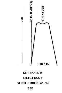 |
• In this system, the exact receiving frequency is correctly dialed when the received signal is demodulated into a side channel separated by ±1.5 Kc from the IF center, and beated with a BFO signal having the same frequency as the IF channel. The distance from the BFO channel (= IF) to the center of the LOWER/UPPER channel gives the correct demodulation (see images below). Note that in the standard SSB system the information resides in the middle, regardless which sideband it is; in the Hammarlund SSB system the information always resides in a side, that's why this system "makes up" an AM reception distribution. The Hammarlund system must be accurately understood and
then adjusted. There are some different alignment instructions in several
versions of the manuals, explanations about design regarding selectivity
and sideband selection are very summarized.
• The IF center of the "X" receiver must coincide EXACTLY with the IF center of the HC-10, IF centers MUST be adjusted with PASSBAND ADJ (slug, on the rear), do not use PASSBAND TUNING KCS to adjust it or as a clarifier. If PASSBAND TUNING is used to do this, the reference to the IF center in the panel is lost, and the heterodyne output signal will not match with the center of the IF chain (this control should match the IF channel at center at "0" dial mark). The usual HC-10 passband setting for SSB is: PASSBAND TUNING to 1 → 1.5 UPPER or LOWER depending on type of sideband (taking into account a possible phase reversal in the receiver), and SIDE BANDS to UPPER or LOWER depending on PASSBAND TUNING dial indication.
• Hammarlund said nothing about having to set the Passband Tuning (misnamed Vernier Tuning on models HQ-170/180) at the +/- dial sides, this control is considered as a clarifier in the manuals, but Hammarlund always was hinting at the need to adjust this system very strictly to get good results. This control was included on the HQ-180 panel after serial #1335, this probably means something important. In the HQ-180/1960-2 modification issue Hammarlund insist about the BFO must be adjusted exactly at IF's center, also insisted on the importance of centering the BFO at zero beat using the calibrator in the 160 meter band selecting 0.5/AM. It makes no sense a mixer centered at 60 Kc when the SSB IF channels are set to 58.5 or 61.5; the mixer also has to offer the incoming signal to the SSB IF chain at each of those frequencies, side by side, and for this it is necessary the Passband Tuning be adjusted on each side.
• Poor and contradictory information, bad understanding and bad tricking are the cause of the bad reputation of this system. Usually the problem lies on not understanding what the BFO is for in this system (not to beat up but to replace a carrier), and how the Passband control should be internally adjusted and externally operated. Trying to adjust the IF chain without taking those aspects into account only leads to a total disadjust. It is also necessary to take into account some errors in the HQ-170/180 "A" manuals, some paragraphs do not consider that the BFO control is disabled in the panel, and when switching to CW, the zero BFO dial mark does not correspond to the IF center; some changes were not properly updated.
|
All capacity values assigned to each SIDE BANDS switching are calculated to work with a 60 Kc IF chain, not any other value! This system has preconfigured input signal processing (sidebandAcenter-IFcenter-sidebandBcenter). Distances between a side to the center may vary at input, but can be adjusted with PASSBAND TUNING (1→1.5 range). When used as SSB converter this preset may not exactly match the IF output of the receiver it is connected to; hence the importance of matching the centers. When connected to a "known receiver" (e.g. HQ-170/180) this handicap disappears, but the exact match of the receiver/converter IFs at center (zero beat) is always mandatory.
|
|
Summarizing: The fundamental difference between the two systems is that in a standard SSB receiver, the SSB signal flows from the antenna to the demodulator input on the carrier channel (in the center), it's the BFO that is placed in the corresponding side depending on SSB signal. In the Hammarlund system the SSB signal flows from the antenna to the input of the last IF also in the center, but from there it is placed on the corresponding side to be demodulated later, and then the BFO replaces the carrier in the center. The last IF has a selectivity and bandwidth system that can process the received signal either in the center (AM-CW) or on one side (SSB).
→ The advantage of the Hammarlund SSB system is that it offers greater selectivity, the disadvantage is that it is more complicated and difficult to adjust than the standard system.
HC-10 Checks/Tests & Operation
Step #1: Setting input frequency at center (*)
- SG unmodulated to input jack, "IF input" = ±455 Kc.
- Function switch to CW/SSB
- PASSBAND TUNING to 0
- SELECTIVITY KCS to .5
- SIDE BANDS to BOTH
- BFO KCS to 0 - Previously adjusted to 60 Kc (T7 slug).
- AVC FAST, AUDIO 3, NOISE OFF, SLOT FREQ KCS 5.
- Adjust L6 (passband adj slug, on the rear) to zero beat.
PASSBAND TUNING: Coarse LO adj, slug = IF input - 60 Kc.
• A-mod: Fine LO adj, trimmer, slotted head at mid capacity. |
Step #2: Checking SSB channels - sideband centers (**)
- Log step #1 frequency at CENTER (UPPER & .5).
- Same positions as in step #1 except:
- PASSBAND TUNING to 1.5 UPPER
- SELECTIVITY to 3
- Adjust SG to zero beat, log SG frequency (UPPER)
- SIDE BANDS to LOWER
- PASSBAND TUNING to 1.5 LOWER
- Adjust SG to zero beat, log SG frequency (LOWER)
- Difference of both with CENTER should be ±1.5 Kc
SELECTIVITY changes should not affect the center-tuned beat. |
(*) The center of the "signal processing area" that this system creates (UPPER+BOTH+LOWER) is the carrier channel in the center of this AM passband area (.5/BOTH).
(**) The center of a sideband is the difference between that carrier channel and the highest/lowest frequency value of that sideband taking into account the selected selectivity. Note that the standard method (shown above) does not have this "hassle", both AM and SSB are received in the center, on the carrier channel.
• SIDEBANDS to UPPER and SELECTIVITY to .5 sets the initial internal configuration base for making frequency selections within the "signal processing area"; .5/UPPER combines the lower capacitance value with the higher impedance load. LOWER is tuned by adding capacitance to the circuit. SELECTIVITY KCS selects the impedance load increase/decrease to the IF stages. The BOTH position selects medium capacitance and low impedance in order to increase bandwidth and creates the center frequency within the passband in combination with SELECTIVITY widths. All component values are calculated to work with an IF stage of 60 Kc. Since 3 is the maximum sideband bandwidth (3 Kc), the sideband centers are ±1.5 Kc apart (UPPER center -1.5 → IF center 0 → LOWER center +1.5). A smaller bandwidth selection brings these sideband centers closer to the center of the system (AM center, carrier channel).
Idealized BOTH and UPPER sideband and selectivity response curves
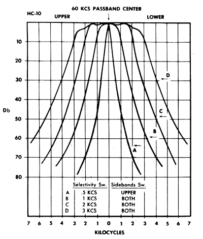 |  |
• The change in frequency from .5/UPPER to .5/BOTH is almost zero, but the UPPER position has the advantage of having less bandwidth. The difference from .5/UPPER to .5/LOWER is about 100 cs, this shows the capacitance change quoted above, small in this case. SSB functional selections begin with SELECTIVITY at 1; SELECTIVITY at .5 is for system setup and CW, only!
As a real example, HC-10 was tested connected to an R-390A: Checking CENTER frequency: (Pass 0 Selec .5 SideB BOTH) = 454.9 Kc (this reveals the exact IF output of that R-390A). Adjusting UPPER sideband at its center: Pass 1.5 Selec 3 SideB UPPER = zero beat is at 453.3 (-1.6 Kc dif). Same on LOWER: Pass 1.5 Selec 3 SideB LOWER = zero beat in the center of the LOWER sideband is at 456.4 (+1.5 Kc dif). PASSBAND TUNING "0" = 454.9; ends are 451.9 & 457.8 Kc (-3.0 +2.9 Kc).
SIDE BANDS and SELECTIVITY switches act ONLY on the 60 Kc IF chain stages, they DO NOT affect the input mixer stage! To be processed, the incoming sideband must be selected using PASSBAND TUNING, converted by the mixer to a low IF of ±60 Kc, and then placed on a side channel in the HC-10 low IF chain. Those "details" is what Hammarlund forgot to clarify! A SSB PASSBAND TUNING KCS selection of 1 → 1.5 fits all SELECTIVITY selections.
Important for correct tuning, and mandatory for sideband tuning using HC-10: PASSBAND TUNING KCS at "0" must coincide with the absolute center of the IF output of receiver "X". When this is achieved, the PASSBAND TUNING KCS dial will show accurate sideband frequencies and sides. Due this, the PASSBAND ADJUSTMENT slug on the rear must be finely adjusted.
Tuning a SSB signal.
The SSB signal is received and processed in circuitry before the HC-10 in the response center of an IF band. To be processed with this system, the signal must be placed on the correct side. To do this, PASSBAND TUNING places the SSB signal on a channel, SIDE BANDS switch adds/removes capacity and SELECTIVITY switch adds/removes load to this channel.
- PASSBAND TUNING to +1.5 or -1.5 depending on sideband. This allows the incoming signal to be to be placed centered on a SIDE channel with SELECTIVITY KCS at '3'.
- SIDE BANDS to UPPER/LOWER depending on PASSBAND TUNING location. This places the signal in the sideband channel that has the correct setting to be processed.
- Mode CW/SSB, BFO KCS "0".
- SELECTIVITY to 3 (maximum sideband width). SSB options by design are 1, 2, 3, only; of practical use: 2 and 3.
- Tune signal with the "X" receiver until maximum intelligibility is
achieved. Very easy if the selected sideband is correct and the HC-10's
SSB system is configured correctly. If the signal cannot become intelligible
change PASSBAND TUNING and SIDE BANDS to the opposite side (sideband indication may result swapped due to a previous phase inversion).
- To check correct operation, change SIDE BANDS. Inverse selection
causes the signal almost disappears or be very attenuated.
• If you need to tweak BFO KCS from "0", something goes wrong, what you are doing misaligns the system even if the adjustment made makes the signal understandable. In this system the BFO is only used to adjust the CW pitch.
• Reception tuning and signal clarification must be done with the receiver, not with the converter.
Tuning an AM signal.
The AM signal is received and processed in circuitry before the HC-10 in the center of the response band. To be processed with this system the signal must continue in the center.
- PASSBAND TUNING to 0. This allows the incoming signal to be placed at center.
- SIDE BANDS to BOTH. This selects the IF center and allows the two side channels to be used.
- Mode AM/MCW (BFO is off).
- SELECTIVITY to 3. AM options are 2 and 3; .5 and 1 useless.
- Tune signal with the "X" receiver until maximum intelligibility is achieved.
Tuning a CW signal.
The CW signal is received and processed in the circuit before the HC-10 in the center of the passband; there is no reason nor is it necessary to change its place. The HC-10 manual says the UPPER sideband should be used for CW reception, IMO this is flamboyant and unnecessary.
- PASSBAND TUNING to 0. This allows the incoming signal to be placed at center.
- SIDE BANDS to BOTH, this selects the IF center of the HC-10.
- Mode CW/SSB, BFO KCS rotated a bit off-center: 0.5 (500 cs, any side).
- SELECTIVITY options are .5, 1; 2 and 3 unnecessary.
- Tune signal with the "X" receiver until maximum intelligibility is achieved.
Note: If .5/UPPER or .5/LOWER are used for some reason, you should be aware that there is a pitch difference between these two positions of about 100 cs (note that .5/UPPER is the base system configuration). That's why I recommend opening a centered AM channel for CW reception, which also allows you to use the .5 Kc minimum selectivity bandwidth. A CW signal is usually a carrier-type signal, which is received using the AM channel with BFO ON, it is incongruous to receive it on a sideband as it is said in the manual. Receiving CW on an SSB channel as described in the manual is another one of the Hammarlund weird things that makes this system bizarre when, if understood from the ground up, it isn't. The CW-at-UPPER extravagance was partially corrected in the next model to carry this system, the HQ-170, by indicating the BOTH position for CW on the main drawing but with no explanatory text. Later, in the manual of the HQ-180 model, it was already clearly indicated in the drawing that the position of SIDE BANDS for CW is BOTH. These changes show that even at Hammarlund there were doubts about how this SSB system worked.
|
Oscillator's checkpoints.
- Converter mixer (LO): PASSBAND TUNING KCS control. Use a frequency
counter capacitively coupled to L6, frequency depends on position of the
PASSBAND TUNING control; when the HC-10 is centered for 455 Kc, the LO mixer will be ±395 Kc.
- BFO: Lateral stator lug of C57 variable capacitor inside chassis,
use a frequency counter capacitively coupled to this lug, frequency depends
on position of the BFO KCS control, BFO center should be ±60 Kc.
Testing current adjusted IF value and BFO synchronization.
- Set AM/MCW, SELECTIVITY .5, SIDEBANDS BOTH, BFO 0, AVC FAST, AUDIO 3, NOISE OFF; all other controls are out of test.
- Connect a VTVM or a DVM adjusted to check a negative DC low voltage to the AVC and GND rear strip connectors (IMO in this case a VTVM will be better due to the graphical effect of the needle). The negative AVC voltage increases in direct proportion as the signal is being tuned.
- Injecting the test signal into the HC-10.
- Strict method, HC-10 outside cabinet: Connect a simple wire with an insulated alligator clip to the output of an RF generator located in the band in which the IF value is estimated. Bite the alligator clip to the input wire (without striping it) to the plate of the first tube of the IF chain (V1 pin 5, this is the primary of the first transformer of the IF chain. WARNING! 250 volt DC here! No stripe wire or make contact! This forms a capacitive coupling of a few picofarads, usually it is enough, the less coupling the better. Then connect the ground of the generator to the HC-10.
- Quick'n dirty method, HC-10 inside cabinet: Use the INPUT jack on the rear to inject the test signal. An input of 60 Kc will pass SLOT FREQUENCY due the circuit is out of resonance; also the heterodyne results of PASSBAND TUNING (the mixer) are out of resonance of the low IF chain, only the input frequency has resonance. This is the option stated in the manual.
- Sweep frequencies with the generator (unmodulated) around 60 Kc locating the frequency that has response in the VTVM or DVM, set it up to maximum indication. This reveals the center frequency of the "carrier channel".
- Log SG frequency, this will be a very approximate value of the low IF. Change to CW/SSB, BFO always at "0").
- If the SG frequency coincide with the frecuency of the BFO there will be no heterodyne sound = zero beat; the value of the low IF is = to the BFO frequency with absolute accuracy (a very low obscure beating sound also indicates accuracy).
- A light tone will indicate frequency mismatch, but if the mismatch with the first log is some cycles no action is required. If the difference is more evaluate adjustment; better and easier to do it in the BFO. The frequency value of the low IF is not important, the important thing is to take into account that LOW IF in the center must be = BFO in the center. Knowing the exact value of the low IF allows to apply it to the calculation of the slug of PASSBAND ADJUSTMENT (mixer LO) = Input IF - Low IF value.
- The best is to have the HC-10 IF chain to 60 Kc with .5/BOTH and PASSBAND at 0 = 60 Kc IF output, the "carrier configuration".
BFO alignment.
- Option A: Use the quick'n dirty method of above to inject a 60 Kc signal. Set CW/SSB, PASSBAND TUNING and BFO KCS 0, SELECTIVITY .5, SIDEBANDS BOTH. Adjust T7 for zero beat.
- Option B: Set CW/SSB, use a capacitively coupled frequency counter to T7; set it to 60,000 cycles read from the frequency counter.
Additional tests.
The SLOT FREQUENCY KCS frequency is set internally. This circuit causes a moving null in the entire passband when L1 is set at current IF center. When the input IF is changed, this setting must also be changed by adjusting its coil slug through the side hole of the case. Position #5 (any side) effectively disconnects this circuit when adjusted at the current HC-10 IF center, the standard position for this knob is #5. The correct operation of SLOT FREQUENCY is to produce a maximum null right in the center of the current IF, the depth of this null is set by SLOT DEPTH.
To test sideband selectivity and separation tune a medium/low strength SSB station; when the sideband selector is switched to the other sideband the station must almost disappear. If this cannot be accomplished there is bad receiver-converter coupling or the HC-10 SSB system is badly adjusted; this also affects the audio response, of course.
I do not recommend to use oscilloscope and sweep generator to fine adjust this system, the empirical method is much better. Using visual instruments it will soon be discovered that nothing remains well adjusted for the multiple SIDE BANDS / SELECT KCS switch combinations because this system can easily have asymmetric responses due to component values; a compromise must be made among frequency responses. Better do it 'live' and 'on-line' by connecting the converter to a trusted (i.e. well adjusted) receiver. As an example, when adjusting this system in the HQ-170/180 models (same circuit as HC-10), the best tool for making fine adjust is the Crystal Calibrator of the "X" receiver and the BFO of the HC-10; test SSB stations, and center the system performing the "noise test" explained on the pages of the HQ-170/80 receivers. A similar procedure should be done with an HC-10 and an "X" receiver; this assure an excellent result.
For an accurate adjustment of this sideband/bandwidth system, a good understanding of how it works is mandatory. The intention of all the pages of this site dedicated to the "Hammarlund SSB brothers" (HC-10, HQ-170, HQ-180) is to "deconstruct" the system a bit in order to clarify it, since all the manuals have poor, and even contradictory information (when reading them gives the feeling that not even Hammarlund knew exactly how this system worked). If this system is accurately adjusted works very-very well, but accuracy is essential; it is not possible to skip the precision in the adjustment.
|
Conclusion on the operation of this SSB system
The system designed by Hammarlund for SSB reception is unusual and a bit confusing, this explains the huge number of HC-10 and HQ-170/180 that when operated by their owners and do not obtain the desired results begin to make 'adjustments', and the only thing they achieve is to disrupt the system (luckily many of them did not fiddle on adjustment of the IF chain). All Hammarlunds that uses this SSB system I have worked on had BFO and Passband (Vernier) Tuning retouched and badly adjusted. In fact Hammarlund has responsibility on it because does not explain in detail the system pretending that the user simply do not have to do anything, just retouching the Passband (Vernier) Tuning control as if it were a kind of band spread control, and precisely bad setting of this control causes bad operation, system starts to get mismatched, then the user starts with BFO touch-ups and the disaster begins: "U" / "L" band separation is being lost and reception becomes critical and confusing, only strong signals will be heard well.
After the initial setup, HC-10 requires minimal operation while connected to a receiver. Fine tuning should always be done with the receiver using the band spread knob, NEVER with the converter via PASSBAND TUNING KCS or BFO KCS. If the HC-10 needs continuous touch-ups, the HC-10's SSB system is not well adjusted; but when properly adjusted does not need touch-ups and remains static (no BFO tweaks or continuous Passband Tuning adjustments). There is no band spread operation on the converter and no fine tuning procedure; fine-tuning is possible with the converter, but it must be clear that if it is done, the system is being misaligned. On SSB the best results will be obtained when the system is focused on one sideband, both in the input (PASSBAND TUNING) and in the corresponding 'process channel' (SIDEBANDS/SELECTIVITY).
An example to use this converter is to connect it to a HQ-160,
which IMO has an IF output dedicated to the HC-10. Although the HQ-160 has very good selectivity combined with good signal to noise ratio (due to the Q multiplier), also good operability, both can be improved with the HC-10, and the sum HQ-160 + HC-10 will result in a kind of "HQ-180 approximation",
or a kind of "HQ-160 on steroids", with some cost in audio response/dynamic range. The last pic in the gallery on the schematics page shows the HC-10 setup required to work with the HQ-160 receiver. |
|

