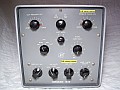
~ HC-10 Pictures (A-mod) ~
|
|
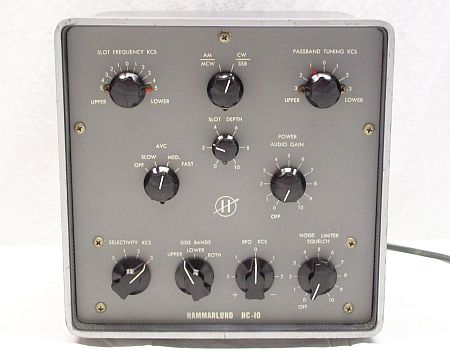
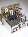
— For comfortable use in Europe this unit has been modified similarly to model "A" HQ receivers: 115/230 AC power line options, but most important is the inclusion of fine tuning of the input frequency, in this manner the PASSBAND TUNING dial on panel becomes accurate at center, thus providing the correct location information to accurately balance the sidebands.
— The new power transformer only outputs 6.3 volts for the tube rectifier filament, so I initially had to upgrade the power supply to solid state because the "5Y3 tube with 6.3V filament" (6AX5 or similar) was not yet available(*). 6AX5 is electrically equivalent to 5Y3 but with different filament voltage, pinout, and cathode output. With 6AX5 available, the circuit returns to the original. The new transformer allows the HC-10 to be used in the EU without the hassle of a step-down transformer.
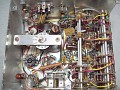
— When this unit was purchased, the coil L6, which is the oscillator of the Passband Tuning, was found broken and loose inside the device, the slug was found also broken (see warning at bottom about Hammarlund forms and slugs). I had to dismantle this coil and assemble the winding on another Hammarlund form that had its own slug, original form and slug were useless. These coils tend to overtighten the slug and, therefore, stiffen its movement, so it is recommended to be very careful when adjusting them (see bottom of page). Most likely the previous owner broke it when trying to adjust it.
(*) For those who might be interested in "solidifying" the HC-10's power supply: The rectifier tube can be replaced by 2 x 1N4007 (or 4006/5/4) silicon diodes inside an octal plug; and an optional capricious "pilot lamp" connected to the unused 6.3 VAC line may be installed on top. Modifying a power supply to solid state usually increases B+, therefore a 300 ohm / 10 µF smoothing cell was added at the input of the B+ AC smoothing filter to reduce the extra output voltage, thus restoring the original voltages.
The "A-mod" consists on the following:
- The main modification has been
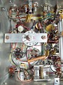
made by adding fine passband adjustment to the existent coarse adjustment, original design uses the Passband Tuning control for fine adjustment. In this system the input bandpass MUST BE ABSOLUTELY ACCURATE, and this can not be achieved adjusting a tight or loose slug. A device that allows exact adjustment will be very good, an air trimmer is perfect. It was installed using the rear hole used for the phones connector.
- Now the 'controlled AC' outlet is used as the AC mains input connector, and the hole for the mains cable is used for the phones connector. As a bonus, that connector is now in a more convenient position on the right corner for connecting phones.
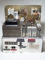
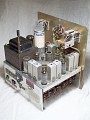
- The original 115-only transformer was replaced by other that combines primary windings to operate on several voltages. This new transformer features 110/125/220-230 VAC input with 300-0-300 to rectifier, 6.3 to rectifier filament, and 6.3 to filaments line. The 6.3 volt output for the rectifier tube forces the change from the original 5Y3 rectifier tube to the equivalent 6AX5 tube. A long screw of this transformer (see pic above) was used so that the unit can stay flat upside down, which is very good for mods and checks.
- As the Noise Limiter tends to distort just when connected due to the lack of negative voltage that in a complete receiver (e.g. HQ-170/180) the stages before the low IF provide, an adjustable bias source is added to compensate for this lack of voltage, thus setting the NL bias threshold. See below.
|
~ Schematics ~
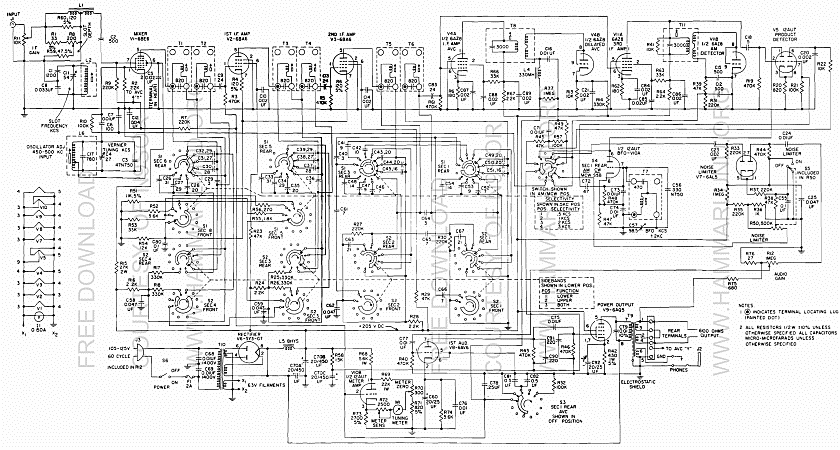
| HC-10 |
 |
| |
| SPC-10 |
 |
| |
| HC-10 noise limiter schematic with NL-ON distortion correction |
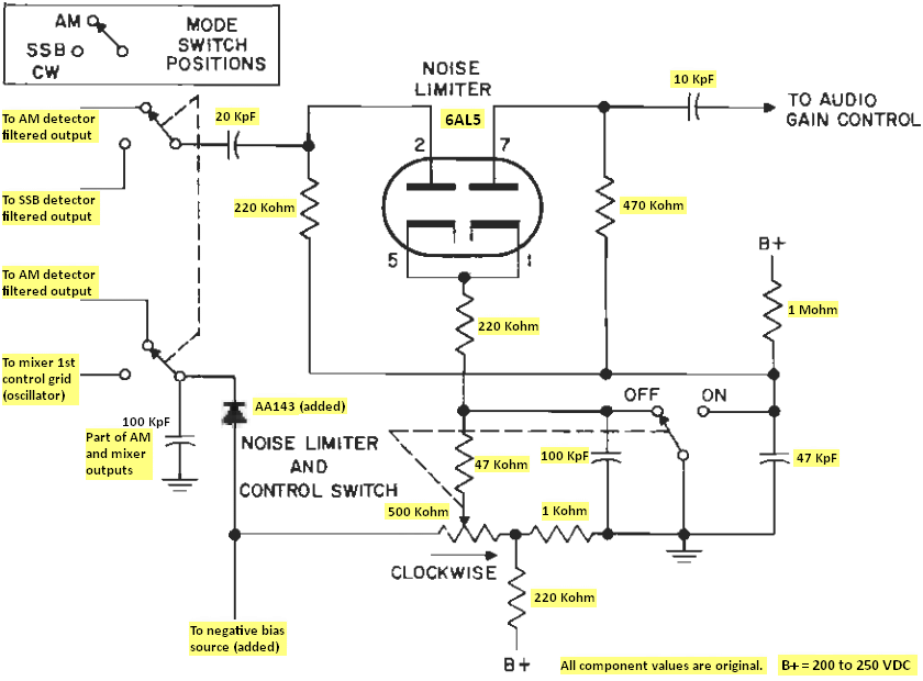
Above: HC-10 noise limiter adapted to work with a bias source that adjusts its clipping threshold.
The HC-10 NL distorts just connected, this is due to the lack of negative bias that exists when this NL is operated in a complete receiver. The HC-10 is just the low IF chain, detector, and audio circuits of a receiver (specifically Hammarlund HQ-170 and HQ-180).
Standard Features:
- OFF position: B+ voltage to 6AL5 plates, cathode to ground potential.
- ON position: 6AL5 plates to ground potential, B+ voltage to 6AL5 cathode.
- When the cathode is more + than the plate (or when the plate is more - than the cathode) more clipping.
- The 220 Kohm resistor plus the 1 Kohm resistor forms a voltage divider to neutralize the diode contact potential.
Added Features:
- A negative voltage from a bias source is included to set the initial clipping threshold (see pic below), the output voltage should set to about -4 volts after the warm-up period.
- A germanium diode (AA-143, or similar) is included to block negative voltage from the bias source to the HC-10 circuit, but allowing the negative bias from the HC-10 circuit to flow to the noise limiter. This diode acts as a "voltage direction traffic light" keeping the negative voltage of the bias source isolated from the HC-10 circuitry, this voltage only affects the noise limiter circuit.
- The bias source described below, or similar circuit, allows the use of this noise limiter in any receiver. The germanium diode and associated switch positions can be removed, then the output voltage is adjusted so that in ON and at the minimum position of the potentiometer (low bias) there is no signal distortion.
The 100 KpF capacitor on the left (C56, HC-10 schematic) is part of the filtered AM (V4, 6BV8) and mixer (V1, 6BE6) outputs, it is not part of the noise limiter circuit, as in the HC-10 schematic it seems that it is. It's probably there for dimensional reasons, and for the same reasons it was replaced by a 'tropical-fish' capacitor, space has to be made to install the 'traffic-light' diode.
|
| |
| A bias source to set the initial threshold of the HC-10's noise limiter |
 Hover over the image to see the back.
This bias source works in combination with the AA143 diode (see circuit above). Red wire: Connected to a rectifier tube plate (a secondary HV-AC winding of the PS transformer). + 1N4004 diode + 47 Kohm resistor + 5 Kohm potentiometer to ground shunted with a 47 µF, 63 volt electrolytic capacitor.
Yellow wire: Adjustable output from 0 to -7 volts. The terminal strip holder is soldered to a ground terminal.
See pics in the gallery above showing this bias source installed. |

Preventive info on Hammarlund coils
— Coil cores (slugs) with hexagonal hole can be damaged easily!
The screw pitch
of these coils may be very hard to be adjusted and the coil form or
the ferrite core can break, also, in a frequent retouch, the ferrite
thread and/or the thread inside the coil form can wear down running too
loose causing variations on tuning after the radio has moved. Unnecessary fiddling
can damage threads of coil cores or worn-out coil grooves.
Hammarlund slugs have an hexagonal hole that passes through its center, oftentimes what appears to be a stuck slug is actually a broken slug. Never force a slug with a tool that allows some play, you'll ruin that slug if it tends to get stuck. The tool must slide perfectly in the slug; if you try to use an hex tool that allows some rotation before engaging, it can break that slug during the adjustment travel, this will permanently seize up the broken slug into the coil. These slugs usually become splitted in two along its hexagonal hole, the hex bar tool used to adjust separates the broken halves by pressing them against the wall of the coil form: when turned harder, the halves grip the wall of the coil more tightly. That's why when a slug seems "freezed" or "sticked" never must be forced, since there is a potential risk that the whole coil will twist inside itself and tear off the wires coming off the coil to the connections base. If the slug is hard but ain't broken use a very solid and rigid hexagonal bar that fits exactly to the central hole of the slug. A broken slug should be carefully removed (destroyed) using the tip of a needle, and then replaced.
— "Excessive" modern design on Mixer-Converter & IF transformers!
In later Hammarlunds
the coils are modern at the best and worst meaning of the word, that is,
the form factor is designed to provide a high Q, but design criteria to
avoid manual labor are also used as well as cheap material (plastic). Someone
thought that the tuning capacitors were installed using built-in open construction
mica insulated caps and that could be located in the plastic mounting base
connected using the usual solder lugs of the coil (internal ends are moulded
like a clamp), and these ends were used to make contact by surface pressure
on the mica. The result is that the reliability over time of these transformers
depends on how careful that was the mounting employee to avoid forcing
or twisting these solder lugs and not heating them too much when welding.
If this occurs, contact pressure is weakened, this creates a "variable
resistor" in series with the tuning capacitor, and the results are: a permanent
loss of gain, a sporadic sound like storm static, or sudden changes in
volume. The solution is increase pressure if the contact surfaces are
not affected, or deleting the "modernity" installing normal sealed caps.
The issue due bad pressure contact may be confused with another issue: The Hammarlund popular "Silver Mica Disease".
|