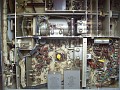
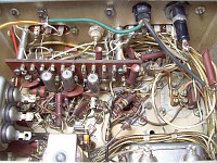
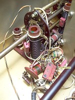
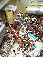
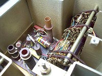
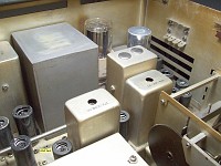
Click thumbnail to preview, click image to enlarge.
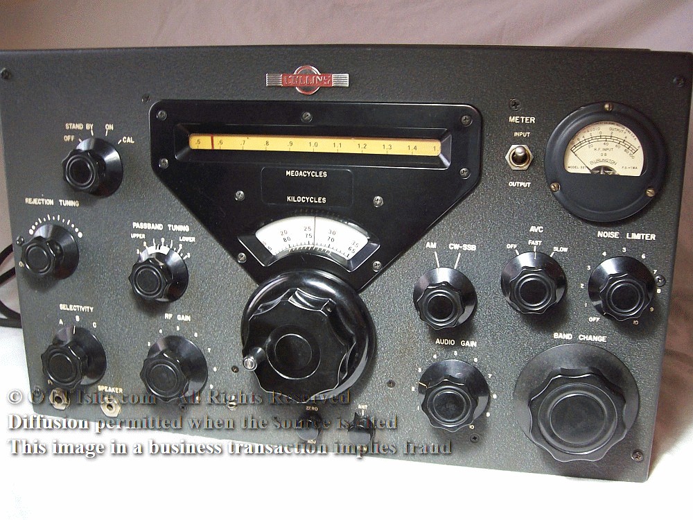
Collins 51J-5, General Coverage SW Receiver.
51J-5: The unreleased successor of the 51J-4 and 'big brother' of the 75A-4.
Frequency coverage:
Total: 0.5 to 30.5 Mcs in 30 numbered bands (odd/even) of 1 Mc.
* 0.5 to 1.5 Mcs (Triple Conversion).
* 1.5 to 3.5 Mcs (Single Conversion). * 3.5 to 30.5 Mcs (Double Conversion).
Design type & Intermediate Frequencies:
Converter design except on 1.5 to 3.5 Mcs that is mixer design.
Tunable IFs: TWO depending on band number (1 to 30).
* ODD bands (1, 3, ...29): 2.5 to 3.5 Mcs.
* EVEN bands (2, 4, ...30): 1.5 to 2.5 Mcs.
Fixed low-IF: 500 Kcs.
6DC6 RF amplifier, AGC operated.
6BA7 1st Mixer (converter design).
6BA7 Band 1 Mixer (0.5 to 1.5 Mcs, MW broadcasting band).
6AK5 Local Xtal Oscillator, converter design to the mixers above.
6BA7 2nd Mixer.
6BA6 + 6BA6 Variable Local Oscillator (PTO).
6BA6 1st 500 Kc IF amplifier, AGC operated.
12AX7 Q multiplier. Null notch operation only (CW use).
6BA6 2nd 500 Kc IF amplifier, AGC operated.
6BA6 3rd 500 Kc IF amplifier, AGC operated.
6BA6 4th 500 Kc IF amplifier, AGC operated. 6AL5 AM/MCW Detector and AGC (AVC) rectifier.
12AT7 500 Kc IF output / AGC (AVC) DC amplifier. 12AU7 SSB/CW Product Detector.
6BA6 Beat Frequency Oscillator (BFO).
6AL5 Noise Limiter.
12AX7 AF amplifier, (thus the 'correct tube' was installed here, see 75A-4 page).
6AQ5 AF output.
6AL5 bias rectifier / RF Gain bias gate.
5R4 power rectifier, a Chatham "potato masher" type.
0A2 Voltage regulator.
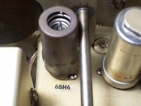
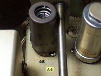
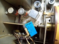
6BA6 Calibrator... mislabeled as 6BH6 (see pics). 6BH6 is what was marked on the chassis and found installed, but as the pics show, it is a misinterpretation of the label hand writted by the designer. DEFINITELY a mistake, 6BH6 does not have the HF response that a tube used as a calibrator needs,
due this, to force HF response, someone put a wire across the 1 Kohm B+ filter resistor to boost the voltage to the calibrator circuit. 6BH6 is replaced by 6BA6, the correct tube, and the crossover wire is removed. On wanting to increase the calibration signal output, the most practical option is to install a 6DC6 or 6BZ6 as a calibrator tube. Both the 6CD6 and 6BZ6 are 200V B+ tubes, not 250V like the 6BA6, but since the B+ line of the calibrator is 170 volts, there is no need to do anything other than replace the tube; the pinouts of the 6DC6 and 6BZ6 tubes are compatible with the 6BA6 calibrator design.
PASSBAND TUNING:
Tunes the UPPER range, center 0, and LOWER range of a +3 Kc to -3 Kc frequency area centered at 455 Kc. Located in front of the mechanical filters, therefore the effective bandwidth of this frequency area depends on the bandwidth of the selected mechanical filter. To perform passband tuning efficiently, the response of this frequency area should be as flat as possible. Note: Tuning is reversed on bands 2 and 3, set PT at UPPER to receive LOWER sideband, and at LOWER to receive UPPER sideband.
SSB operation, 3.1 mechanical filter:
* 80 & 40 meter bands (lower SB): PASSBAND TUNING set at 1.5 Kc LOWER.
* 20 to 10 meter bands (upper SB): PASSBAND TUNING set at 1.5 Kc UPPER.
* 160 meter band, 1.8 Mcs (lower SB): PASSBAND TUNING set at 1.5 Kc UPPER because the phase correction logic operating on bands 4 to 30 and 1 does not match the phase correction required on single conversion bands (2-3).
AM operation, 6.0 mechanical filter:
Function switch to AM, AVC FAST, PASSBAND TUNING at center '0'.
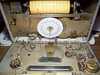
FM operation, slope filter with slanted sides: Artisanal, see the last pic in the series below.
Function switch to AM, AVC FAST, PASSBAND TUNING at center '0'.
* UPPER sideband: Low Frequency heterodynes, left of center; HF right.
* LOWER sideband: Low Frequency heterodynes, right of center, HF left.
The opposite for bands 2 and 3.
RF GAIN:
Adjusts the gain of the IF chain an also has influence on the signal to noise ratio.
IF GAIN ADJUST → AVC THRESHOLD:
R9 adj-pot (75A-4 sch), associated with the overall adjustment of the receiver, not for continuous retouching. When receiving signals, adjust R9 to the best signal-to-noise ratio.
Noise Limiter (SB-2 version of the 75A-4's NL):
Service Bulletin #2; dated October 15, 1956, but without the NL OFF option. This gives a clear clue as to when the 51J-5 began to be designed, necessarily after that date.
I/O impedances:
Antenna: Nominally 50 to 150 ohms; but other impedances may be used.
Audio: 4 ohms speaker, external 600 ohm line, phones.
IF OUT: cathode follower circuit, 50 ohms.
Power Supply, transformer, mains operation:
Double primary: Parallel connection 115 VAC, series connection 230 VAC.
Secondary: 5 VAC filament to 5R4
6.3 VAC filament to the rest of tubes
700 VAC center-tapped to 5R4 plates (350 + 350)
100 VAC (350 section tapped at 100; 350-100-ground-350)
B+ outputs (±)
240 VDC to the audio power output tube
170 VDC to the calibrator, screen grid of the 1st mixer, and band 1 mixer
140 VDC to the product detector circuit
210 VDC to the rest of the circuits (main B+ line)
Bias outputs (±)
-90 volts at the output of the bias rectifier
-30 volts at the factual output to the RF GAIN (AVC) line
Audio strip.
G: Ground.
M: External audio muting operation. #5 ground terminal of the audio transformer (connected externally to G by default).
4: 4 ohm output for speaker (no out when phones plugged into phone jack).
600: 600 ohm output for audio line applications.
Control strip.
G: Ground.
DL: Unconnected. I use it as a diode load terminal for adjustment, since the original diode load terminal is difficult to use (now the original DL terminal is used to check the operating side of the BFO depending on the even/odd bands). R: This terminal is combined with the ON and CAL positions releasing the high muting bias and providing an operational ground to the receiver. By default it should be connected to G. Provides external Stand-By mode operation, and can be connected to the active contact of a send-receive relay.
Antenna connector. (Max RF input is 50 VAC!)
BNC connector, but changed to SO-239 UHF connector for better compatibility and ease of use. Same antenna characteristics as 51J-4. → 51J-5 does not have the K101 break-in relay that the model 4 has, therefore the max RF input must be taken into account!
Mandatory tools for knob removal
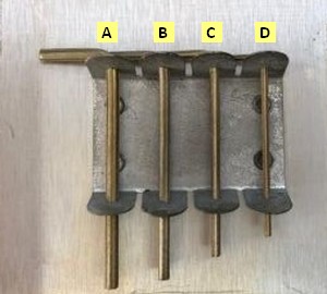
B • Daka-Ware knobs, skirt up to 2-1/16" for Collins: → Use Bristol spline L-Key S-096-6 (.096 inch - 2,44 mm thick - 6 flutes+). D • Collins vernier knob 4 to 1 (also ring gear & pinion collar mechanism): → Use Bristol spline L-Key S-060-6 (.060 inch - 1,52 mm thick - 6 flutes+). A • Daka-Ware 3" skirted knob, standard Collins main tuning knob (1955): → Use Bristol spline L-Key S-111-6 (.111 inch - 2,82 mm thick - 6 flutes+). C Internal PTO coupler: Bristol spline L-Key S-069-4 (.069 inch - 1,75 mm thick - 4 flutes+). +) Be$t buy on Max-Gain Systems, SS-508 wrench kit features.
Bottom cover:
Fixed to the case with 8 medium-sized screws and to the dividing panels with 13 small-sized screws.
Production (pre-production)
Two pre-production fully functional test units (X1 and X2) plus the factory design prototype unit (which is normally kept in the factory for possible checks and modifications). There is no official documentation on this receiver. As the last Collins 75A-4s were produced at Collins Canada's Bermondsey plant in Toronto, the 51J-4 successor was also started at this plant during 1957 and 1958. These X1 and X2 units were widely used by the US and Canadian military respectively. It is clearly noticeable, see the heat mark of the original 5R4 "potato masher" in the X2 unit (it takes a lot of use for that mark to occur). They were most likely decommissioned 10-12 years later, in early 70s. The US unit was later auctioned, the canadian unit has a peculiar history, and the factory's design and testing unit was most likely destroyed.
Collins 51J-5, info on unit X2:
51J-5 unit X2 is in the Hammond Museum (related to Hammond Mfg) in Guelph, Ontario. See 'The Signal' magazine, issue 71 of Q3 2013 at CCA. BTW: Some of the statements about the operation of phase reversal correction on both even and odd bands are not correct. I think they have not realized that the circuit they perceive to be missing is already present, I can see it in the photos included in the article... maybe in unit X2 that circuit is not working properly.It would have been a considerable botched job to send to the military the receiver with that deficiency, there is no point in testing a receiver with this "issue", they would have kicked it back and the engineer would have looked incompetent. Both the X1 and X2 units appear to be heavily used, so they had to be in perfect working order when the military used them.
Mechanical maintenance:
Very small amounts of sewing machine oil or firearm oil can be applied on these locations, there is no need to use 'MIL specialties'.
Purpose: This set of articles attempts to provide an objective analysis and
description of a very unknown receiver that was designed to succeed the model 51J-4 but never entered into production due to Collins' marketing shift to the 'S' line. The intention with all the devices on this site is that they can be used normally (no criteria of collecting or nostalgia), therefore all the pages are written with the intention of serving as an aid for the review of old devices by their owners (some basic electronics knowledge and skills are required, of course). In this case that intention is impossible because this receiver never went into mass production, the maximum number of confirmed owners is two*; maybe three if the factory test'n design unit has survived**. But since this model has the same RF design as 51J-4 it shares common alignment procedures (in fact it is a 51J-4 upgraded with the SSB circuitry of 75A-4), many comments and explanations are also helpful for 51J-4.
*) And one of them is a museum. **) See 'A bit of history' page.
Important Note:
Due to the unique characteristics of this receiver and taking into account its manufacturer, in order to prevent misuse of the images (e.g. using them in a fake internet sale or auction), there is a copyright notice on each image, but they may be used freely for technical or informational purposes.
Block structure: 51J-5 is a mix of 51J-4 + 75A-4 circuits See below for the complete RF to AF sequence and origin of the circuits.
Circuit stage, name.
Origin
Comments (Through this sequence of circuits you can get an idea of the 51J-5 schematic)
Antenna/ RF amplifier
51J-4
6DC6 instead 6AK5
First mixer
51J-4
6BA7 instead 6BE6
Band 1 mixer
51J-4
6BA7 instead 6BE6
Xtal oscillator (Local)
51J-4
6AK5
2nd Mixer, input tuning coils.
51J-4
(1)
PTO (LO to 2nd mixer)
51J-4
6BA6 + 6BA6
2nd Mixer + Mechanical Filters
75A-4
6BA7 instead 6BE6
1stt IF amplifier
75A-4
6BA6
Rejection Tuning
75A-4
12AX7
2nd IF amplifier
75A-4
6BA6 (but without the S-Meter circuit).
3rd IF amplifier
51J-4
S-meter circuit, (meter is 0-1 mA, 46 ohms; thus at 1 mA end scale 46 mV).
4th IF amplifier
51J-4
S-meter circuit, (when power ON, S-Meter receives 96 mV).
AM detector
75A-4
6AL5 (1/2)
SSB detector
75A-4
12AU7
BFO
75A-4
6BA6
AGC source
—
6AL5 (2/2) Exclusive circuit, similar to 51J-4 but without RF GAIN operation.
AGC amplifier (DC Amplifier)
—
12AT7 (1/2) Badly retouched by someone (see pics below). AVC circuit rebuild page.
IF Output
51J-4
12AT7 (2/2)
Noise Limiter
75A-4
6AL6
Audio preamplifier circuit
75A-4
12AX7 (75A-4 has 12AT7 but circuit is for 12AX7, it seems Bratsberg also realized this).
Audio output circuit
51J-4
6AQ5
Audio output features
51J-4
Audio jacks on panel.
Power Supply
51J-4
5R4, "potato masher" type, instead 5V4.
Power supply features
75A-4
100 VAC output for the bias rectifier circuit, and 3x32µF filter capacitor instead 2x35µF.
Bias Rectifier
75A-4
6AL5 (associated to RF GAIN operation).
Calibrator
51J-4
6BA6 (51J-5 has 6BH6 installed but it is a labeling mistake, see pics below).
(1) 51J-5 follows the broadband trend of the 75A-4 due to the existence of PASSBAND TUNING, although here this trend is less because the front-end and RF block of the 51J-5 is the same as the 51J-4, it is not designed in a simplified way as it happens in the 75A-4, so these circuits have Q.
Circuit details and previous citations:
Some comments and comparisons with 75A-4 (and 51J-4):
51J-5 has the same RF GAIN operation layout as 51J-4 (and 75A-4). This control is located on the panel because it serves to regulate the sensitivity of the receiver depending on the actual propagation conditions of the band in use. It should not be set fully clockwise by default relying on the AGC to automatically correct level differences (to set it this manner it would not be necessary to place it on the panel). An S-Meter is an indicator of the strength of the received stations which reflects the sensitivity of the receiver and the level of propagation. When the sensitivity is reduced with the GAIN control, the S-Meter should act accordingly, it should decrease... not increase!!!. That's the surprising part on many Collins receivers and others who have copied the "system" (e.g. Heathkit). This "system" has become so normalized that it is believed that this is the correct operation, and it is not; what the S-Meter reflects is the increase in the AGC bias voltage. This is a cheap system to control the sensitivity of a receiver, in fact there is no a true sensitivity control because if the gain is reduced the S-meter no longer provides S units of incoming signal, but rather an internal voltage level; it's absurd. See the difference when operating a Hammarlund receiver: AGC line and
GAIN control are separated, thus more gain, more S-Meter indication, less gain, less S-Meter indication; the S-Meter always provides S units of incoming signal, which can be attenuated by operating the gain control, that's the right operation. For SSB reception, the best performance is achieved by polarizing the AGC line a little, to do this RF GAIN must be set to 9 instead of 10 (S1 on the S-Meter).
Since I have been forced to redesign the AVC source circuit (see text above), in this unit it is almost no longer necessary to touch up RF GAIN. The AVC (AGC) time constants have been increased both in FAST and SLOW positions, so it is perfectly possible to operate constantly with RF GAIN at maximum.
The biggest difference on design with 75A-4 is that the 51J-5 does not have the simplification of the RF circuitry that the 75A-4 has, by avoiding this simplification Q is improved. 51J-5 has an improved front-end tuning system (exactly the same as the 51J-4). The proof is that when the 6DC6 tube in the 51J-6 RF amp is replaced by 6GM6, there is hardly any difference, while in the 75A-4 the "magic" happens. The 6GM6 is a pure wideband circuit tube, if the "magic" effect does not occur it means that the design of the stage does not have wideband characteristics. Another example of circuit/tube adaptation would be the input stage of the Heathkit HW-100, when 6AU6 is replaced by 6HS6 the same "magic" happens, but this magic is not caused by the tube, but by tube/circuit adaptation, if this coincidence does not occur replacing "normal" tubes for "hot" ones only entails more current consumption. For a tube to give the result of the design, that tube must be surrounded by the appropriate circuit; and for optimal performance it must be matched to the circuit.
51J-5 shares the same "Collins design" with 75A-4, that is, converter+mixer design = using high frequency wideband converters and a low frequency mixer (which is what gives frequency stability and accuracy). The converter+mixer design tends to be noisy because the pre-frequency tuning circuitry is wideband, allowing frequency tuning at low intermediate frequencies (IF). This allows the use of a low-frequency local oscillator (LO), which is key to frequency stability in tube receivers. This combination allows Collins receivers to avoid frequency drift, although at the cost of being noisier than those using the mixer+converter design (the classic Armstrong design, e.g. Hammarlunds). This tendency toward noise impacts signal-to-noise ratio, which is a drawback of the converter+mixer design. So much of what I mentioned for the 75A-4 persists as a tendency. Both in 75A-4 and 51J-5 these tendencies should be eliminated by proper selection of mechanical filter bandwidth and by the use of PASSBAND TUNING.
Like 75A-4, 51J-5 relies too heavily on the mechanical filter, depending on one or the other a different receiver will be obtained. This high dependency is very criticizable because the only thing that allows to customize bandwidth and Q are mechanical filters. Furthermore, the noise actually perceived depends entirely on the bandwidth of the inserted mechanical filter: more space around the signal, more perceived noise; less space, less perceived noise.
There are no waxed paper capacitors in the 51J-5, the only ones made of paper are PIO (paper in oil), which are much more reliable, so I have not had the need to make a page dedicated to capacitors like the one for the 75A-4. Several Vitamin Qs have been tested and after more than 60 years they give very good results on the capacitor tester. The medium capacity bathtub type (0.1 µF) gives incredibly good results, the high capacity ones (20 µF - bias source filter) give worse results but I think this is because the Heathkit C-3 is not designed to test these capacitors, as they are somewhere between electrolytic and standard paper capacitors. The only capacitor that has had to be replaced is the AC filter electrolytic capacitor, but not because it was leaking, but because it was completely dry (thus AC hum). This capacitor is triple, similar to the 75A-4, but since a NOS 51J-4 AC smoothing capacitor (double) has been found, that double has been installed plus an independent one for the product detector line, therefore the AC smoothing filter design has changed from being like the 75A-4 to the original 51J-4.
The only capacitors that could cause problems (as with the 75A-4), are the EL-MENCOs silver mica. So far, the only silver mica capacitor found to be defective is C121 100 pF (75A-4 schematic) which runs in series from the BFO tube grid to the BFO L/C tank. The problem is exactly the same as the one found on the 75A-4: fluctuating (fluttering) capacitance effect that causes pitch variations in audio (in this case) and detuning of the signal in other cases. Issue is that the BFO frequency increases for a certain time (about 1000 cycles) and after another indeterminate time decreases for a similar number of cycles in a random manner. This cannot be caused by the voltage, since it is low at that point. It is replaced by a styroflex capacitor of the same capacity; now the BFO is rock solid.
Disregarding the error in the tube used, the calibrator circuit of the 51J-5 is the same as that of the 51J-4. The CAL adjustment on the panel operates the 100 pF variable capacitor C224 (51J-4 schematic), but surprisingly, its effect on frequency variation is minimal, adjustment range is less than 10 cycles (so why has it been placed on the panel?). To adjust the CAL frequency at 100 Kc the 5-25 pF trimmer C169 must be used with C224 at half capacity, the capacitance effect of C224 is so minimal as to be practically useless, so there is not much point in having this adjust on the front panel.
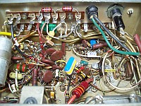
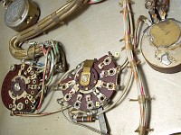
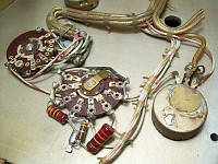
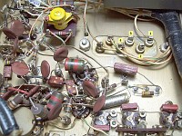
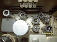
Since there is no schematic for this receiver, I had to use the 75A-4 schematic together with the 51J-4 schematic, and then draw parts of the 51J-5 circuit. The floating board above the circuit in the AF and detection compartment, apart from being an option that should be avoided whenever possible, made signal tracing and voltage measurement at tube sockets extremely difficult or impossible. This board has been redistributed into an 8-point terminal strip on the side wall (and there are even two terminals left over). I didn't even need to make any holes, since there were two free ones that also matched exactly with those on the terminal strip. Now everything is accessible, the circuit can be traced, and all voltages can be checked. In the first pics above you can see the before and after of the detection, NL/AF circuits, bias, rectifier tube, and audio power output compartment. The NL/AF circuits are identical to those of the 75A-4. Capacitors C115 and C102 from the original 75A-4 circuit, which are not strictly necessary, were missing, I suppose due to lack of space, but now they can be installed and the circuit is exactly the same as in the 75A-4.
The completely dry filter electrolytic capacitor, the NL board, and some replaced components can be seen in this photograph.
Note: The above 51J-5 ↔ 75A-4 comparisons are made by comparing original designs. When 51J-5 is compared with 75A-4 with 6GM6 in the RF amplifier and with the IF dynamics tweaked, there is not so much difference.
51J-5 ↔ 75A-4 ↔ 51J-4 comparisons and conclusion: The Collins 51J-5 receiver is a modernized 51J-4 with Passband Tuning and the SSB circuitry of the 75A-4. 51J-5 has a similar number of tubes to the 75A-4 (23 vs 22), which can be confusing when comparing them, as they look identical; the difference is that the 51J-5 has more frequency coverage and it does not have the simplified front-end RF circuitry of the 75A-4, but rather the more complete one of the 51J-4. It also has an additional IF stage (the extra tube), which improves Q, therefore 51J-5 is less affected by the noise of the band in use than 75A-4. The improved signal-to-noise ratio of the 51J-5 relative to the 75A-4 becomes increasingly apparent with increasing frequency, resulting 51J-5 has better effective sensitivity than 75A-4. 75A-4’s functional contributions included in 51J-5 (single-sideband circuitry and passband tuning) make 51J-5 superior to 51J-4. As with the 75A-4, the passband tuning works excellent as interference killer, routing the interfering signal to the mechanical filter vertical skirt, thus completely eliminating interference.
Only two units of this model (#X1 and #X2) were built, in addition to the factory test model, at Collins-Canada. This is the 51J-5 #X1, which delivers excellent performance on all bands and in all modes, ready to work, and with all its functions working perfectly; except some dial inaccuracies due lack of PTO linearity. The 51J-5 #X2 rests in peace in the Hammond Museum of Guelph, Ontario, Canada.