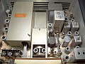
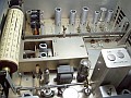
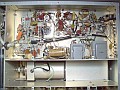
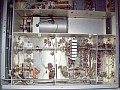
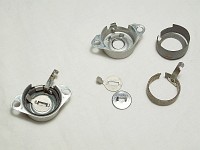
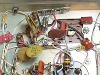
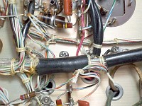
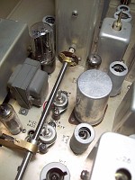
Click thumbnail to preview, click image to enlarge and get slideshow.
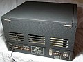
Collins 75A-4, Amateur Bands + CB Receiver.
Frequency coverage:
→ 160 meters: 1.5 to 2.5 Mcs (Single Conversion++).
→ 80 meters: 3.2 to 4.2 Mcs (Double Conversion).
→ 40 meters: 6.8 to 7.8 Mcs (DC).
→ 20 meters: 14.0 to 15.0 Mcs (DC).
→ 15 meters: 20.8 to 21.8 Mcs (until June 1957, DC). → 15 meters: 20.5 to 21.5 Mcs (after June 1957, DC).
→ 11 meters: 26,5 to 27,5 Mcs (Citizen Band, DC).
→ 10 meters: 28.0 to 29.0 Mcs (DC).
→ 10 meters: 29.0 to 30.0 Mcs (DC). ++) Due to SC this range may be affected by underlying 'signals' from powerful commercial Medium Wave broadcast stations (image frequencies from 540 Kcs to 1.5 Mcs).
Modes:
AM/CW/SSB/MCW.
Tube line-up: 22 tubes.
6DC6 RF amplifier, AGC operated.
6BA7 1st mixer, mixer of the converter circuit on DC, RF amp on SC.
12AT7 Local Xtal Oscillator, DC, converter design.
6BA7 2nd mixer, THE mixer on SC.
6BA6 + 6BA6 Variable Local Oscillator (PTO).
6BA6 1st 455 Kc IF amplifier, AGC operated.
12AX7 Q multiplier. Null notch operation only (CW use).
6BA6 2nd 455 Kc IF amplifier, AGC operated.
6BA6 3rd 455 Kc IF amplifier, AGC operated.
6BA6 455 Kc IF amplifier, AGC (AVC) amplifier only.
6AL5 AGC (AVC) Detector only.
6AL5 AM/MCW Detector & Muting gate.
12AU7 SSB/CW Detector.
6BA6 Beat Frequency Oscillator (BFO).
6AL5 Noise Limiter.
12AT7 AF amplifier (12AX7 optional+++).
6AQ5 AF output.
5Y3 Power Rectifier.
0A2 Voltage regulator.
6AL6 Bias rectifier & Bias gate.
6BA6 Calibrator.
+++) Circuit values are fully compatible with 12AX7 (ECC83). In fact, it appears that these values were initially calculated to use 12AX7 instead of 12AT7. A production mistake? Note: If you want to attenuate low audio response to have a midrange effect simply switch to 12AU7, that's all. The 12AU7 low Ri will automatically do the job as its low value of plate resistance will not balance with the current circuit values to give equivalent response.
Design type & Intermediate Frequencies:
Converter design except on 160 meters that is mixer design.
Tunable IF of 1.5 to 2.5 Mcs, fixed IF of 455 Kcs.
Local Oscillator (PTO) output frecuency:
1.955 Kcs to 2.955 Kcs.
Selectivity:
Depending on the bandwidth of the 455 Kc mechanical filters. All bandwidths are centered on 455 Kcs.
PASSBAND TUNING:
Note: Tuning is reversed on 160 meter band.
→ Set PT at UPPER to receive LOWER sideband.
→ Set PT at LOWER to receive UPPER sideband.
Tunes the UPPER range, center 0, and LOWER range of a +3 Kc to -3 Kc frequency area centered at 455 Kc. Located in front of the mechanical filters, therefore the effective bandwidth of this frequency area depends on the bandwidth of the selected mechanical filter. To perform passband tuning efficiently, the response of this frequency area should be as flat as possible. It works wonders at eliminating interfering signals, it's truly amazing, the interference literally "falls" into the "recycling bin".
75A-4 performs TRUE PASSBAND TUNING: (and differences with the fake one)
→ True Passband Tuning is the ability to make the received signal "sightsee around" the IF passband, incorporating frequencies on one side and suppressing them on the other without losing the tuning of the received signal... and that's why the IF response must be completely flat... and that's why this characteristic affects the signal-to-noise ratio and the signal dynamics.
→ Fake Passband Tuning consists solely on exploring the received signal in the IF passband, usually with the intention of selecting its sidebands e.g. like in Hammarlund HC-10. HQ-170/180 receivers labels it as VERNIER TUNING, which is more appropriate but also confusing and therefore often misinterpreted by the user.
RF GAIN operation: (Extremely important control on this receiver!)
It is CRUCIAL that the operator of a 75A-4 understands the effect of adjusting RF GAIN on this receiver, as it is directly related to the "flat AVC characteristic" described in the manual, which is also directly related to the SIGNAL-TO-NOISE ratio level that this receiver can offer.
At that time, this lack of understanding led to a multitude of modifications that improved some things on one hand, but worsened others on the other.
Pls remember that OTTTsite checks old gear for possible current use, not for collecting or decorating a hamshack.
→ Due to the AGC design feature, 75A-4 cannot operate on SSB at max RF GAIN while handling signals of very different strengths due the 75A-4's AGC will only correct signal levels within a specific range. In other words, 75A-4 cannot be operated "appliance style" (RF GAIN knob at max) because this would produce syllabic "pops"; this limited AGC characteristic led to many COMPLAINTS and subsequent HAM MODS.
→ RF GAIN setting greatly influences signal-to-noise ratio. The procedure to take advantage of that with proper SSB reception involves a 'two-handed operation' to minimize the 75A-4's features of low signal-to-noise ratio and short AGC. Left hand on RF GAIN and right hand on AF GAIN: decrease RF gain so that the S-Meter increases until it reaches signal peaks achieving a minimum level of band noise (this matches received signal with 75A-4's AGC characteristic, placing the noise level at the AGC starting point with RF GAIN), then adjust AF GAIN to the best audio level; in fact, this is what Collins recommends in the manual (see secIII/par3-d).
IF GAIN ADJUST → AVC THRESHOLD:
Potentiometer R9 on the chassis, front area. Associated with the overall adjustment of the receiver, not for continuous retouching. When receiving signals, adjust R9 to the best signal-to-noise ratio.
SSB operation, Ham Bands 3.1 mechanical filter:
80 & 40 meter bands (lower SB): PASSBAND TUNING set at 1.5 Kc LOWER.
20 to 10 meter bands (upper SB): PASSBAND TUNING set at 1.5 Kc UPPER.
160 meter band (lower SB): PASSBAND TUNING set at 1.5 Kc UPPER (due to single conversion, the converter circuit is not working in SC). When using more selective filters (e.g. 2.1), PASSBAND TUNING should be adjusted somewhat backward, about 1 Kc Lower/Upper.
AM operation, 6.0 mechanical filter:
Function switch to AM, PASSBAND TUNING at center '0'.
REJECTION TUNING, SSB operation:
UPPER sideband: Low Frequency heterodynes, left of center; HF right.
LOWER sideband: Low Frequency heterodynes, right of center, HF left.
Reverse the effect on the 160 meter band.
ANT TRIM:
Fine tuning adjustment of the antenna stage (RF stage). It begins to have operational effect starting the 20 meter band onwards. Due to its low capacity and the broadband response of the RF stage, its operation is hardly evident on 40, 80, and 160 meter bands.
I/O impedances:
Antenna: Nominally 50 to 150 ohms; but other impedances may be used.
Audio: 4 ohms speaker, external 500 ohm line, phones.
Power Supply, transformer, mains operation:
Primary: 115 VAC only. EU use (230) requires step-down transformer.
Secondary: 5 VAC filament to 5Y3
6.3 VAC filament to the rest of tubes
600 VAC center-tapped to 5Y3 plates (300 + 300)
100 VAC (300 section tapped at 100; 300-100-ground-300)
B+ outputs (±)
Bias output (±)
210 DC to the audio stage
110 DC to the product detector circuit
180 DC to the rest of the circuits
-35 volts at the factual output of the bias rectifier (C-115)
Audio strip.
P: 4 ohm output for phones. G: Ground (common). 4: 4 ohm output for speaker (no out when phones plugged into phone jack). 500: 500 ohm output for audio line applications.
Muting/Stand-by strip.
M: Break-in muting voltage input, at least 20 VDC key-down, zero key-up. G: Ground. 1 & 2: Stand-by terminals to be connected to the contacts of a send-receive relay (the OFF / STD-BY / ON / CAL switch should select STD-BY).
Antenna strip. (Max RF input is 50 VAC!)
1: Single-wire antenna (2 & G must be connected to ground). 1 & 2: Balanced antenna, grounding G may introduce noise (important!). G: Ground.
Mandatory tools for knob removal.
• Daka-Ware knobs, skirt up to 2-1/16" for Collins: → Use Bristol spline L-Key S-096-6 (.096 inch - 2,44 mm thick - 6 flutes+).
• Collins vernier knob 4 to 1 (also ring gear & pinion collar mechanism): → Use Bristol spline L-Key S-060-6 (.060 inch - 1,52 mm thick - 6 flutes+).
• Daka-Ware 3" skirted knob, standard Collins main tuning knob (1955): → Use Bristol spline L-Key S-111-6 (.111 inch - 2,82 mm thick - 6 flutes+). Internal PTO coupler: Bristol spline L-Key S-069-4 (.069 inch - 1,75 mm thick - 4 flutes+). +) Be$t buy on Max-Gain Systems, SS-508 wrench kit features.
Collins vernier tuning knob reduction gear
• Releasing the PTO tuning shaft from the 4:1 vernier mechanism (mandatory for front-panel removal):
→ Loosen the two Bristol screws of the big Collins vernier tuning knob using Bristol spline L-Key S-060-6. It takes some patience to insert the Bristol tool into the head of the Bristol screw due to the perimeter distance.
→ Carefully remove and save that big tuning knob. Made of Bakelite!!! If it falls to the ground it will surely break.
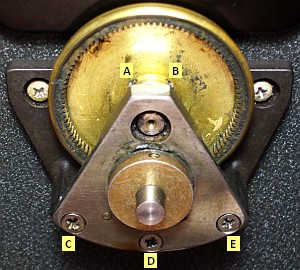
→ Loosen Bristol screws A and B of the ring gear using the same Bristol tool (S-060-6). See pic on the left.
→ Remove and save C, D, E, Philips screws.
→ Carefully remove and save the gear mechanism combo (ring gear & pinion collar mechanism). Can be removed separately. In fact, the entire mechanism can be removed, but IMO it is better for the 4:1 mechanism that the frame casting stays in place and not disturb the two retaining screws, since the frame is exactly centered with the axis of the PTO shaft and the anti-backlash system puts pressure on this shaft.
Bottom cover.
Fixed to the case with 16 medium-sized screws.
Service Bulletins.
SB#1 (Dec/1955):
a) Add contact potential bias to the noise limiter.
b) Q multiplier redesign from 12AT7 to 12AX7. Important!
c) Eliminate random fuse blowing.
d) Keep RF out of muting circuit.
SB#2 (Oct/1956):
a) S-Meter sensitivity potentiometer replacement.
b) Mod to reduce Hum.
c) Adding effectiveness to the noise limiter for high frequency pulses.
SB#3 (May/1957):
a) S-Meter redesign. Important! See my particular implementation below.
SB#4 (Sep/1957):
a) Elimination of RF pickup while in standby position.
Production.
From Mar-1955 through Oct-1959 (6,000 ± units).
Production changes (undocumented).
Antenna plug:
• Type-N, SO-239, BNC; alternating among production groups. IMO, SO-239 is the most suitable.
Early-production change:
• The first unused V19 second diode is added to the RF gain circuit to the AGC bias line as voltage gate.
Mid-production changes:
• Skirted main tuning knob to 4:1 gear reduction knob. Important! It implies the 'Dial Drag' to 'Dial Lock' lettering change.
• IF gain adjust: polarization by voltage divider instead resistor to ground. Recommended.
• B+ removed from the input coil of the mechanical filters. Important!
• 15 meter band frequencies from 20.8/21.8 Mcs to 20.5/21.5 Mcs, this implies LO xtal change from 23.3 Mcs to 23 Mcs. Note 23.0 Mcs is standard xtal production.
→ Due to the wideband design in all stages, 75A-4 is highly sensitive to noise, it may be necessary to use the less sensitive to noise antenna.
→ Due to the low Q factor of the 75A-4's 455 Kc IF transformers, the best mechanical filter under noisy conditions would be the one that provides a 'sock-type adaptation' to the received signal, thus removing adjacent noise (e.g. a MF of 2.1, not the standard 3.1). Using a tight fit mechanical filter helps to mask the low signal-to-noise ratio design feature.
→ Due to the low signal-to-noise ratio 75A-4 is not adapted to receive weak signals, but when a band is low noise, the 75A-4 will perform wonderfully and be able to show off its sensitivity.
→ The signal-to-noise ratio worsens from the 15-meter band onwards due to the design of the front-end stage. Starting at the 40-meter band, the signals are tuned using the 40 meter coils shunted with others to achieve resonance up to the 10 meter band; this design reduces Q and therefore dynamics as frequency increases (see align page, bottom).
→ As medium to strong signals crush noise, when receiving these signals, 75A-4 performs EXCELLENT, but it may be necessary to operate RF GAIN (what the manual recommends, and that's what it's on the panel for). Note: Ignoring this leads to a very popular complaint: 75A-4 has "poor AGC action". It is not exactly so, what it has is a strictly adjusted AGC to signals between a minimum and a specific maximum, what Collins calls "flat AGC characteristic" in the manual (4-4; what is said in 3-3 should also be consulted; also see the Collins note 'Souping up the 75A-4').
→ CB FM stations in the 11 meter band (or any other band) cannot be tuned using slope detection because the skirt of the MFs is too vertical.
→ The big advantage over other receivers is great frequency stability, dial accuracy, and mechanical quality.
Signal-to-noise ratio figure and its real-world application: The signal-to-noise ratio is a value that causes numerous disappointments when subjected to harsh reality, and has become a cliché that only generates misunderstandings; in fact, it is a fallacy. The factual signal-to-noise ratio is the difference between the received signal level and the noise level in the band in use that the speaker shows, not with the electronic processing noise of a device (usually very low until we get to VHF). Therefore, measuring the s/n ratio with an RF generator, which obviously does not generate real band noise, is simply a reference to the design quality of a device, but not an operational parameter because the variable to be considered is another type of noise. Of course, band noise varies, so there will be different signal-to-noise ratios depending on band conditions. To avoid this, a signal generator is used, but defining operational s/n ratios based on an RF generator is a farce because it does not consider the actual noise coming in from the antenna. Therefore it is advisable not to get obsessed with electronic s/n ratios, which are useless in the real world. A device may have acceptable internal noise level, but unacceptable external noise handling. The true s/n ratio is the dynamic s/n ratio, that's why I refer to the concept of "noise processing ability" on the 75A-4 modifications page, and that's why the 75A-4 can go from being a very good receiver to a mediocre one depending on band noise... but when the RF stage switches to 6GM6, it abandons mediocrity. Ultra-high transconductance tubes (EF183/6EH7, 12000 µmhos; EF184/6EJ7, 15000 µmhos; 6GM6, 13000 µmhos; etc.) were designed to work in video circuits, they are the only way to achieve adequate s/n ratios with large bandwidths that, for its own nature, have A LOT of noise.
Signal-to-noise ratio, pentagrid mixer tubes, and 75A-4: The signal-to-noise ratio as a cliché is closely associated with the so-called "pentagrid" tubes. These tubes have 5 grids, in addition to plate and cathode, so they would actually be heptodes; they were specifically designed for mixing operations. The people who designed them knew what they were doing, as demonstrated by the fact that virtually all HF communications receivers have mixing tubes, exceptions are scarce; there are no frequency issues when processing intermediate frequencies (and higher) with pentagrid mixer tubes. Having more internal elements logically generates more operating noise, but this noise is well below the signal they process. If a 6BE6 (HQ-180) or 6BA7 (75A-4) produces noise, the mixing circuit is not working properly, probably because the voltages are not scaled correctly when used as mixers/converters, and also because of poor output filtering when used as product detectors. Receiver design plays an important role on noise, especially in a receiver designed with the converter + mixer basis (Collins, wideband front-ends); receivers designed with the mixer + converter basis (e.g. Hammarlund, Q-circuit front-ends) handle much better the noise coming from the antenna. "Pentagrid" tubes are somewhat similar to cathode ray tubes; they require specific voltage distribution across electrodes. When the dual-screen grid voltage exceeds a certain point, these mixer/converter tubes lose conversion efficiency; however, if voltages are correct, these tubes work excellently because they are specifically designed for mixer/converter operation. Also, these tubes allow the use of a low-level LO or BFO, which offers the advantage of injecting less noise, but if the injection is excessive, noise is generated with low conversion efficiency. In other words, things go in the opposite direction to what one might understand (more LO/BFO injection, better conversion / demodulation), and perhaps that's why these tubes have bad reputation, but it's not their fault. When voltages are OK, these tubes provide excellent isolation of the injected signal, such as the LO signal in a receiver or the BFO signal in a product detector. I'm posting these two comments because signal-to-noise ratio and equivalent noise resistance figures have been very popular, but unfortunately, they are often interpreted outside their real context.
Purpose: This set of articles attempts to make an objective analysis of a receiver that is part of the production of a very mythologized brand. It has been divided into a main page, this one, a capacitor review page (a necessity in 50's electronics), a set-up and alignment page, and a page dedicated to the long history of 75A-4 modifications along with some arrangements that I have made. The intention with all the devices on this site is that they can be used normally, there are no criteria for collecting or nostalgia.
The Collins model 75A-4 is a 22 tube single/double conversion (original schematic of THIS UNIT, date mfg July 12, 1956) communications superhet receiver designed on the converter principle, i.e. the LO operation, and therefore tuning, is achieved at the lowest frequency at which the receiver operates, this ensures maximum stability and very low drift on all bands (almost negligible). The frequencies above the lowest frequency at which the receiver operates are transferred through Xtal converters to be tuned into that lower frequency range (that's why drift is negligible in all bands); this was the basis of Collins' "magic".
The manufacturing period of the 75A-4 model can be divided into 3 editions:
First, 1955: Q-Mult mod and 4:1 tuning reduction.
Middle, 1956: Final Noise Limiter mod and some undocumented circuit changes.
Last, 1957: Final S-Meter mod and the undocumented change of the 15 meter band.
The design of this receiver is simpler than it seems, the use of a simplified front-end and mechanical filters have a lot to do with it, in fact the 75A-4 is a 1.5 to 2.5 Mcs Medium Wave single conversion receiver that has a RF front-end line "hacked" (in 'modern' speaking, see the align page) to provide the rest of the frequencies. In this design it is very important that the bandwidth of 1 Mc (2.5 - 1.5) of the input area to the mixer (V-5) has a response curve as flat as possible because it needs to emulate the frequencies as would be received by an antenna, any irregularity of this area will affect all bands. The “hack” of putting a converter system in front of a mixing system was a very popular resource in the 50s, practically all amateurs who wanted to expand reception ranges did it (remember that this was a time when many Hams were electronics enthusiasts, so the level of self-construction or intervention in the device was relatively high).
75A-4 conversion chart sequence (all high-side mixers have phase inversion)
Thus IF signal has the same phasing feature as the input signal
40 meters [6.8→7.8 Mc]
1st mixer (High-Side) 9.3 Mcs Butler XLO
2.5→1.5 Mcs IF
20 meters [14→15 Mc]
1st mixer (High-Side) 16.5 Mcs Butler XLO
2.5→1.5 Mcs IF
15 meters [20.8→21.8 Mc]
1st mixer (High-Side) 23.3 Mcs Butler XLO
2.5→1.5 Mcs IF
11 meters [26.5→27.5 Mc]
1st mixer (High-Side) 29 Mcs Butler XLO
2.5→1.5 Mcs IF
10 meters (A) [28→29 Mc]
1st mixer (High-Side) 30.5 Mcs Butler XLO
2.5→1.5 Mcs IF
10 meters (B) [29→30 Mc]
1st mixer (High-Side) 31.5 Mcs Butler XLO
2.5→1.5 Mcs IF
On single conversion, the 75A-4 is a 1.5 to 2.5 Mcs Medium Wave receiver with comm-tech specialties. This 1 MHz radio can be aligned via the usual methods used to align 5-tube radios, setting the IF and low RF via coil and the high RF via trimmer. The front-end circuit begins with an RF transformer (T1)
followed by an RF amplifier (V-2), which tunes the entire bandwidth of 1 megacycle using the secondary coil of the the RF transformer (this variable inductance is equivalent to a section of the tandem capacitor in mixer-style receivers) to the grid of V-2. The V-2 plate gives output to the signal in broadband operation (untuned) to V-3. On 160 V-3 acts as an RF amplifier using only the high side of the 6BA7 pentagrid converter tube. The output of the V-3 has tuned plate output (L18) and tuned grid input (L22) to V-4 (2nd mixer) separated by a 5.7 Mc trap (L18 and R22 are also parts of a "tandem").
On double conversion a 7-band converter circuit is inserted in the RF line, the single conversion design is 'hacked' (to make it understandable in a current way). The converter-mixer design was very popular among DIY radio amateurs at that time, mainly on high frequencies. This 'hack' consists in an HF converter that operates before the LF mixer. The RF output from V-2 (6DC6) includes a set of coils on the input grid of the pentagrid 6BA7 converter (pin 7 ), which now acts for what it was designed for (converter tube -xtal mixer-), and to complete this its control grid (pin 2) receives a xtal controlled RF signal from a local oscillator (V-4, 12AT7). On double conversion the 75A-4 inverts side bands, but the panel is marked taking this inversion into account; therefore the side band indications on the panel will only be erroneous for the 160 meter band.
455 IF section: The output from the Mixer stage (2nd mixer) is taken via a set of mechanical filters, followed by the first IF amplifier, a
Q-multiplier circuit that has only null (refection) effect drives the signal to a second and after a third IF amplifier. In parallel to the last IF amplifier is the AVC amplifier (AGC) which provides the AVC bias voltage. 6BA6 vari-mu RF pentodes are employed in these IF stages, the three in sequence are controlled from the AGC line. Following these stages are the detectors, an AM-MCW detector, an SSB-CW detector, and an AVC (AGC) detector.
AF and PS section: The output from a signal detector circuit is applied to an optional Noise Limiter, which feeds the 1st triode portion of a 12AT7, which is resistance capacity coupled to the 2nd portion, and this feeds a 6AQ5 tube that loads the output transformer. The power supply circuitry has a power transformer of 115/300+300 with one section tapped at 100 volts to provide voltage to the bias rectifier, B+ is provided by the usual full
wave rectifier with filtered output and parallel heather chain; the noise limiter tube filament has a 10 ohm resistor in series to limit hum from the filament.
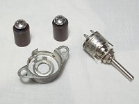
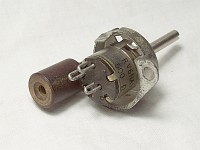
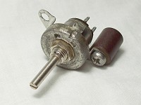
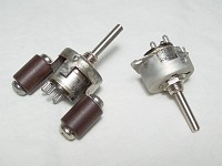
The mechanical filter, the 'heart' of the 75A-4. Without this component, all its special features disappear.
A set of Collins mechanicals filters that can be used in a 75A-4: 0.8 - 1.5 - 2.1 - 3.1 - 6.0 - 12.0 Kc of bandwidth. These are
plug-in filters to be installed in a Noval-type socket (9-pin miniature). 0.8 is the standard for CW, 1.5 is a filter for special circumstances and signals, 2.1 is my favorite for SSB, IMO this filter has a perfect bandwidth to audio combination that greatly reduces noise (which is of great help in this receiver), 3.1 is the standard for SSB, 6.0 is the standard for AM and 12.0 is the broadcasting filter (it would be the filter for commercial stations that can be received within the 75a-4's Ham bands). Manual states that only certain filter codes corresponding to the bandwidths of 0.8 for CW, 3.1 for SSB and 6.0 for AM should be used, but in practice other codes and other bandwidths can be used. As it is noted, there are two heights, and some weigh a little
more than others. The selectivity and acoustic performance (including noise) of the 75A-4 are absolutely determined by the bandwidth provided by the chosen mechanical filter. PASSBAND TUNING uses the vertical side-cut characteristic of these filters to make the interfering signal disappear by 'dropping' it through the cutoff.
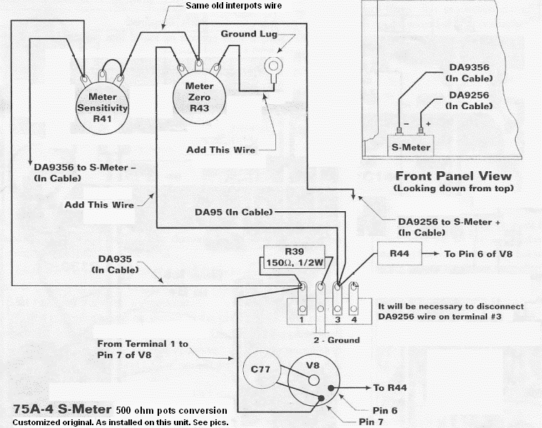
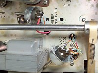
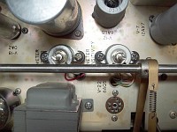
Service Bulletin 2A S-Meter circuit implementation, but with the original overchassis mounting design.
This applies to units below SN 3423. Mouse over to see actual S-Meter wiring
No internal mounting plate required for potentiometers, no overcrowding an already crowded circuit area (mouse over the graph). Only two more phenolic spacers are needed; I have used a couple of these, but they don't need to be phenolic, can be metallic.
Collins oddities and 75A-4 thoughts:
RF GAIN is a control that is located on the panel because it serves to regulate the sensitivity of the receiver
depending on the actual propagation conditions of the band in use. It should not be set fully clockwise by default relying on the AGC to automatically
correct level differences (to set it this manner it would not be necessary to place it on the panel). An S-Meter is an indicator of the strength of the received stations which reflects the sensitivity of the receiver and the level of propagation. When the sensitivity of the 75A-4 is reduced with the GAIN control, the S-Meter should act accordingly, it should decrease ... not increase as happens in 75A-4. That's the surprising part on many Collins receivers and others who have copied the "system" (e.g. Heathkit). This "system" has become so normalized that it is believed that this is the correct operation, and it is not; what the S-Meter reflects is the increase in the AGC bias voltage. This is a cheap system to control the sensitivity of a
receiver, in fact there is no a true sensitivity control because if the gain is reduced the S-meter no longer provides S units of incoming signal, but rather an internal voltage level; it's absurd. See the difference when operating a Hammarlund receiver: AGC line and GAIN control are separated, thus more gain, more S-Meter indication, less gain, less S-Meter indication; the S-Meter always provides S units of incoming signal, which can be attenuated by operating the gain control, that's the right operation. For SSB reception, the best performance is achieved by polarizing the AGC line a little, to do this RF GAIN must be set to 9 instead of 10 (S1 on the S-Meter). Collins advises on the AVC behavior in Section III, Tuning SSB signals, paragraph d.
75A-4 is an "squelched radio" when Noise Limiter is ON. This is more a feature than a bug (a voltage threshold is needed for the NL). When the noise is very low, the NL is not polarized and does not open. I don't know if the same thing continues to happen with the SB-2 version of the noise limiter. How to check this feature? The easiest way to check it is to disconnect the antenna, select AM, NL ON: High decrease of background noise. This is because the NL aperture level depends entirely on the RF background noise, not on setting a minimum bias voltage. The SSB position injects the required bias. Don't be surprised if the receiver goes silent after switching to AM with the Noise Limiter in the same advanced position that worked OK on SSB.
75A-4 is not as functionally sensitive(*1) as other similar receivers, but it is a common feature of the converter design due wideband implies less Q.The lack of functional sensitivity is due to the effect of noise on the signal. The converter system needs to compensate for all these drawbacks trying to make the front-end stage as selective as possible, and also increasing Q in the mixing system that follows, but here Collins designed a receiver with very limited IF dynamics, with a "low impedance AVC line to minimize blocking on strong signals", in his own words. But this must be well understood, it means that instead of boosting the AVC so that it can be used with signals of different levels, what it does is compact the level of the signals to adapt them to the AVC line, this makes life less complicated but it is a wrong decision.
75A-4 tends to get noisy and has a very questionable signal-to-noise ratio from 15 meters onwards, but the tendency to be noisy is also a common feature of converter design because it generates a wide area (broadband) at the output so that a mixing stage can select frequencies with a variable local oscillator operating at low frequencies. The noise effectively perceived depends entirely on the bandwidth of the mechanical filter inserted; more empty space around the signal, more perceived noise; less empty space, less perceived noise. Conclusion: the mechanical filter must be exact to the signal amplitude, the "secret" to 75A-4's efficiency.
Why do Collins receivers have significantly less drift than other receivers? → Mixer design versus Converter design. Collins explains it, but omits some aspects on the matter (QST ad related to 75A-4, Oct-1958).
75A-4 relies too much on mechanical filter, depending on one or the other a different receiver will be obtained. This high dependency is very criticizable because there is almost nothing that allows to customize bandwidth and Q upon receiving except mechanical filters. I say "almost" because REJECTION TUNING can be used to cut off a noisy side area of the received signal, resulting in an improvement in the signal-to-noise ratio.
75A-4 has a questionable AVC starting point, this is a design consequence.
IMO excessively delayed with the excuse that it does not act on the noise, but the nature and level of noise are diverse, in fact noise is a
"special type" of signal (*2), so what was said in this note on the subject does not make sense, the real reason has to be something else. 75A-4 needs to increase signal-to-noise ratio, but it should be clear that increasing the S-N ratio will make the current AVC design insufficient to handle a signal with greater dynamics, and will almost certainly require manual action. Although in an unmodified 75A-4 the AVC/SSB system works acceptably good, when receiving strong signals it is advisable to set RF GAIN to 9. There is controversy regarding this, many consider that the AGC (AVC) should cover all signal circumstances, but it is unrealistic to expect an AGC system to cover from a very powerful nearby station to a very weak distant station. Collins instructs on RF gain use in Section III of the manual, Tuning SSB signals, paragraph d (as already stated, this control is intended to be used).
This 75A-4 has been tested in difficult conditions to see if the reputation of the brand brought something new, but the result is a bit disappointing, in reality 75A-4 only performs very well in easy conditions. Connected to an "antenna" made up of a wire of about 2 meters (6.5 feet), when compared with Hammarlund HQ-160 (modified version, see HQ-160 AGC page), HQ-160 wins in sensitivity and signal-to-noise ratio, although 75A-4 wins in frequency stability of course; absence of drift and dial accuracy were the most powerful features of the Collins equipment. The 75A-4 front-end is a simplified broadband design and the IF chain has its Q attenuated by shunt resistors, making the 75A-4 appear to be a "solid brick" with little adaptability to different scenarios. According to Collins, these are design features to achieve flat AVC, but IMO flat AVC is the adaptation to these "features" that cause poor signal-to-noise ratio. To compensate for the broadband characteristic at the output of the converter, high front-end selectivity is needed as the converter heterodyne system only tunes through the front-end. The 75A-4 front end is an economical design that uses coils in parallel from 40 meters onwards (see alignment page, table at bottom), this is a low Q design that has even less Q as frequency increases. When a wideband feature is present, selectivity and dynamic range are automatically affected, both are usually corrected in later stages, but this is not the case here because Q is attenuated again in the 455 Kc IF chain.
IMO the 75A-4 is the last radio Collins made for old school (technical based) radio amateurs, but to their surprise, many of those amateurs were not as accommodating as they thought, and the 75A-4 was subject to a considerable number of Ham mods; so something was wrong with the 75A-4. Today this receiver has very good opinions and blessings, but it's probably more due to the 'Collins myth' and checking the 40 meter band than a complete user experience, being that many 75A-4s end up as an ornament in a Ham shack or keeping company with other equipment in a collection. To preserve something it is mandatory to make it useful, devices like the 75A-4 deserve to be used, and whoever wants to preserve them better think about putting them to use. Nowadays a 75A-4 can be used as long as the issue of paper/mica capacitors has been reviewed, and as long as the user knows what a vintage communications receiver is and what it can do. The S line (1959-1975) was advertised using broad audience marketing principles, it seems that this line was aimed at consumers of high-end appliances, not at clients or technically minded users. The S line anticipated what amateur radio would be in the future, but whether that was for better or worse is debatable.
(*1) That the noise level let the sensitivity become evident. (*2) Not to be confused with the thermal noise of the tube (power-on noise), which is very low compared to the noise that enters through the antenna. What is important is the operational noise, that is, electronic noise resulting from processing signals of all types, including external noise and thermal noise as types of signals. Electronic noise depends on the particular tube design and the frequency being processed (how many times the electrons collide with the electrodes and the speed with which they do so).
Note: Comments above on 75A-4's performance are for the original design and by comparing an original 75A-4 with the performance of similar category receivers of the era. By replacing 6DC6 with a very high transconductance RF tube, and tweaking IF dynamics, the overall performance of a 75A-4 is significantly improved.
Conclusion: This is a receiver whose excellent reputation precedes it, but I think is a reputation based more on the myth of the brand than on an objective analysis, in fact it is very difficult to find out precise opinions on the 75A-4, except, of course, the inevitable references to audio quality (sometimes negative), and the usual admiration for the manufacturing craftsmanship (always positive). The audio quality from a properly functioning 75A-4 is very adequate for communication service, which is what the 75A-4 is designed for. Collins took great care in the craftsmanship of his devices, but what works in electronic equipment is the circuit diagram, not its appearance. What was undoubtedly impressive at its time is dial reading accuracy, frequency stability (both common in all the Collins gear by design), the essential contribution of the mechanical filter, and the peculiar PASSBAND TUNING action to 'throw off' an interfering side signal by letting it fall into the side abyss of the mechanical filter, but 75A-4 performance could be better, especially regarding to signal-to-noise ratio; this is very evident when comparing a 75A-4 with a mixer+converter design receiver. If the S-N ratio issue is taken into account by selecting AT LEAST mid-level signals, and it is considered that the RF GAIN control is on the panel to be used, 75A-4 is an excellent receiver perfectly usable nowadays, but no one should be surprised that a weak signal that can be heard with an average communications receiver that uses the mixing and tuning system on high-frequency (e.g. Hammarlunds, frequency-dependent drift, but very good S-N ratio -excellent when compared with Collins receivers-), cannot be heard with a 75A-4 because it is covered by noise. The excellence that a 75A-4 can show depends on how noisy the band in use is, this happens with all communications receivers of course, but in this regard, it seems that inside a 75A-4 two different receivers coexist in one. When there is little noise in the band, a 75A-4 will offer excellent performance, but in the presence of a lot of noise, a 75A-4 will offer very questionable overall performance, too questionable for the existing noise; that is due to the low Q design of the front-end combined with the flat broadband design of the IF chain. Fortunately, the most modern TV IF tubes with transconductances greater than 10 mA/V help improve the effective Q of a 75A-4 RF amplifier. These tubes did not exist when the 75A-4 was designed (1955), they were designed to be used in very wideband circuits, when used in narrower band circuits they either make no difference or cause problems. Replacing 6DC6 with 6GM6 (1960), or any other very high transconductance tube, substantially improves the signal-to-noise ratio of a 75A-4, and this evidences that the 75A-4's front-end is a wideband design with low Q.