Modifications for the Collins 75A-4 receiver
Example of 'ham spirit' or evidence of poor performance?
75A-4 was subject to a considerable number of mods made by many radio amateurs which reflects an interest in electronics and not only in the use of electronic equipment, but also this large number of mods (a very disturbing large number of mods) may indicate that many 75A-4 users were unhappy with its performance. So many, even Collins had to come into play (Souping Up The 75A-4) to say a popular mod would be counterproductive (but that's how it is? *). Receivers that work OK do not need mods... but perhaps these mods may reflect the radio amateurs of the 75A-4 era knew the difference between “being an enthusiast of” and “hanging out with”... or maybe what happens to me happened to them: Sometimes I look for something to customize reception but there is none, it all depends on the mechanical filters. Reviewing the mods, I have the feeling that the cause of the discontent could have been founded but it was not very focused. The authors of the mods almost never clearly explain the reason that led them to make the mod, but then they show important modifications that really transform the receiver (there is even a mod that renames it to 75A-4*A*). My impression is that the defects observed have to do with the noise level and the signal-to-noise ratio combined with the behavior of the AVC, but they don't clearly say: "Yeah, this is the problem". I will try to clarify this by analyzing the matter of the mods and its evolution.
*) In fact, those pioneers who realized the problem of the 75A-4 were IMO the ones who provided the correct solution, see below. Others tend to follow solutions that do not go to the source of the problem, but rather to solve it with something that compensates for it. The source of the problem is lack of Q in the front-end, associated to an IF with Q restricted by design, so noise becomes relevant when the signal is of low size. Only medium to strong signals avoid the problem.
~ Foreword ~
Noise: Perhaps there is a misunderstanding regarding noise. Noise is usually associated with the internal (thermal) noise of the tubes, but up to 50 Mcs (±) this noise is little compared to the noise that enters through the antenna and interacts with the tubes. More significant is bandwidth noise (less bandwidth, less noise and viceversa). Up to 50 Mcs IMO the practical thing is to refer to the noise processing ability of a tube, and for this the tubes that perform best are IF tubes for TV and VHF tubes since they were designed to process the enormous broadband noise that is produced in these stages. The "trick" consisted of having a high amplification of what stood out above the noise, and what allows this is called transconductance. But transconductance alone does little, to take advantage of that characteristic the entire circuit must be designed to produce it, so these circuits had to have relatively low plate impedances, but to preserve the life of the tubes that had to be combined with relatively low voltages. Transconductance in pentodes compensates for the loss that occurs due to having a relatively low plate impedance, with triodes it is a little more complicated. The noise characteristic of a tube is important with regard to its amplification, since in the same way that the signal is amplified, so is the internal tube noise, so the lower the noise factor the better, but as the amount of noise that enters through the antenna is much greater, the noise processing ability is what is important. Triode mixers are famous when it comes to noise, it seems that they solve everything, but although they have high conversion transconductance they have very low plate resistance (impedance). This is serious because Q is reduced, and consequently the gain of the stage, this increases bandwidth, thus increases noise; of course less noise is perceived, but because there is less gain. The solution to the noise problem goes far beyond theoretical considerations, many times what is evident in theory is not the case in practice.
RF GAIN: Due to the compact range of the AVC circuit, the 75A-4 is not designed to operate at maximum RF gain by default, a signal with a certain dynamic will exceed that range. Collins talks about how to handle it for SSB reception in the manual: "Readjust the RF GAIN control until the S meter kicks up not to exceed three S points or 20 db with the voice modulation. I the S meter kicks much more than this with the modulation, a popping or pumping effect will be observed due to the neccesary attack time of the AVC".
But the procedure I use is:
- RF GAIN fully clockwise.
- Without receiving signal (only noise) adjust the RF gain backwards until the S meter just rises in level.
- Set the RF gain to just below that increment (just below top noise level).
- This procedure, in addition to controlling the level of an SSB signal, increases the signal-to-noise ratio because the noise is located at the elbow of the tube loading line.
- The effectiveness of the procedure depends on how many tubes there are under AVC, the more the better, that is why AVC control in the RF step is important since it is the first circuit that processes noise. Removing AVC level from this tube (and others) is never a good idea since noise is in fact a form of signal, and most of the noise comes in through the antenna.
- The same operation that has been done with background noise can be performed when receiving a signal. It's about placing the noise at the elbow of the tube load line and ensuring that the signal is at the beginning of the ascending line. The RF GAIN should be set to the point before the maximum signal level on the S-Meter. This will do the "magic" of increasing the signal-to-noise ratio of the 75A-4 for a given signal and will also eliminate any "pumping" effect.
Manufacturers do not put RF GAIN on the panel for decorative purposes, a communications receiver should not be managed as if it were a household appliance.
6BA7 tube: This tube was designed to handle signals in the FM range (VHF), this means that it is designed to handle frequencies above those that the 75A-4 handles. Its HF companion, the 6BE6 tube, works very well at the frequencies that the 75A-4 handles, so the 6BA7 should work well (at least) handling signals that the 6BE6 handles without problems. I think this tube is accused of problems that are generated in front of it (the front-end stage), not in it. Being a hexode there will be noise, but not enough for that noise to be decisive (just like what happens with 6BE6). The replacement of the 6BA7 may be questionable since the 75A-3 has 6BA7 mixers and no one complained about it, there must be something else causing problems with the 75A-4. There are modifications to replace 6BA7 with a double triode (the famous "Pullen mixer"), with a pentode (1/2 6U8, 1/2 6EA8) and even with a beam deflection heptode (7360). In the case of the triode, it will most likely lose some gain, due this noise decreases giving the impression that the S-N ratio increases, but there is simply less gain. In the case of the pentode perhaps S-N is gained without losing gain, and in the case of the 7360 hexode I think we simply enter the stylistics without further ado. These modifications involve touching up connections with wires that are not only soldered, but also 'sewn' in the lugs and then pressed with pliers (MIL style). I don't like doing botched jobs leaving pins with cutted wires and then making soldering over them. The pins must be free of cutted wires, this involves a lot of patience, time, and almost surgical work.
75A-3 vs 75A-4: There are no records that its predecessor, the 75A-3, had so many complaints... so what has changed from the 75A-3 to the 75A-4? 6BA7 tubes? 75A-3 has same type of mixer tubes. Design to adapt mechanical filters? 75A-3 has also provision for MFs... now all that remains is for PASSBAND TUNING to be the alleged culprit. 75A-4 most drastic modifications aim to replace the RF tube, the first mixer, and the second mixer, these modifications also have variants. There are also mods to increase IF dynamics and AVC hang time, all of this means that the original Collins' design for the 75A-4 will be significantly modified, and it reveals dissatisfaction with this receiver as it was designed by Collins.
Reports on tube receivers, and also mods, should always be made after the user knows what they are dealing with and when a repair has already been made if necessary, it is foolish to give quality opinions, or design mods, on receivers that need to be repaired; e.g. there are many audio reports that simply reflect that the SSB system is not adjusted OK, but it is generally interpreted that there is a problem in the audio stage. I have needed some documentation to make this article. My experience is to some extent similar to what AJ7O described on Electric Radio, but I wouldn't recommend doing the K7CMS mods by default, only if it is necessary. I attach this article here because it gives a real, non-mythologized image, of what can be expected when purchasing a 75A-4. His explanations on the dipped mica capacitors are really helpful, but remember, there are 60, if one fails in one radio in another radio may be fine, it's not about knowing names, you have to check them. His article is far from the usual articles on Collins equipment that, rather than talking about technical descriptions, seem to talk about legendary stories.
~ 75A-4's modification table ~ Ham mods intended to improve 75A-4 performance (that I have documentation).
| Year |
Subject |
Author |
Elements |
Description |
Comments |
| 19?? |
S-N ratio. RF, IF, AVC. |
unknown |
RF tube change
R46 out |
Souping Up The 75A-4 |
Collins talks on some Ham mod and 75A-4 design. |
| 1960 |
New 2nd mixer |
W6QFE
W6PKK |
6BA7 to 6U8 (pentode) |
- Hexode to pentode redesign.
Claims that "increases S-N ratio, ends pumping when RF gain is run wide open, and no loss of gain is experienced". |
CQ mag. This mod is possibly influenced by 75S-1 that has 6U8 in 1st/2nd mixers. |
| 1962 |
RF tube change
New 1st mixer
IF dynamic range
Audio feedback |
W2JT |
6DC6 (a remote-cutoff tube) to 6FV6 (a sharp-cutoff tube)
6BA7 to 12AT7
IF resistors R29 out, R46 out.
Audio R71 out, R109 to 750K. |
- Trying to increase dynamics throughout the radio.
- Great increase in IF dynamics by removing IF shunt resistors R29/46 (specifically unrecommended by Collins in his note!).
An in-deep continuation of the previous mod. This mod is the origin of the K2GL mod (see below). |
CQ mag. These two mods were the pattern for all subsequent mods that affect the 75A-4 design. |
| 1964 |
7360 mixers |
W2QWS |
6BA7s to 7360s |
Replacing mixer tubes by beam-deflection tubes working as mixers. |
QST mag. IMO a stylistic mod based on the recent (at that time) 7360 tube. Unnecessary. |
| 1965 |
New 1st mixer
New 2nd mixer
IF tube change
Deleting AVC control from IF stages!!!
V6 6BA6 to 6DC6!!!
Increasing AVC time constants. |
K6SHA |
6BA7 to 12AT7
6BA7 to 6U8
V6 6BA6 to 6DC6
No AVC on V6 and V9
New RC time constant components |
- Copy of the above mods but including major changes to the AVC that, it looks like to me, range from dubious to outlandish.
- This mod contains the origin of the K7CMS AGC mod (increasing hang time without increasing moment of silence when switching STDBY to ON), see below. |
CQ mag. Author claims "with the mods 75A-4 is hard to beat as a top-notch receiver". 6DC6 to replace 6BA6? Removing AVC of some IF tubes to eliminate pumping? Removing AVC to V6 and V9 and then creating a heavy AVC time constant to compensate for it? |
| 1965 |
RF tube and both mixers |
KM1H and others |
6DC6 to 6GM6
6BA7 to 6ES8 (ECC186)
6BA7 to 6AW8 (pentode) |
- Combined design of the other previous ones. |
Source: scattered info from the internet. Interesting. |
| 1965 |
RF tube, both mixers, 455 IF gain, audio feedback |
K2GL |
6DC6 to 6GM6
6BA7 to 6DJ8 (ECC88)
6BA7 to 6EA8 (pentode)
IF resistors R29 and R46 out.
Audio R71 out,
R109 to 750K. |
- Modernized version of the 1960 and 1962 mods.
- Great increase in IF dynamics by removing IF shunt resistors R29/46 (specifically unrecommended by Collins in his note!).
- Compensated audio feedback: output transformer secondary increases and plate-to-plate decreases. |
6EA8 change possibly influenced by 75S-3 that has 6EA8 1st/2nd mixers.
- K2GL, Hazard "Buz" Earle Reeves, Jr. was a pioneer in sound electronics and a personal friend of Artur Collins.
A quite calculated mod. |
| 1967 |
75A-4*A* |
W2VCZ |
6DC6 to 6GM6.
6BA7 to 6DJ8 (ECC88).
6BA7 to 6EA8 (pentode).
5Y3 to diodes (optional).
IF resistors R29 & R46 out. |
- Slight variation of the previous mod and radio renamed to '75A-4A'.
- Great increase in IF dynamics by removing IF shunt resistors R29/46 (specifically unrecommended by Collins in his note!).
- Very similar to the previous one. |
These two similar mods are the preferred by 75A-4's restorers like W3HM, Howard Mills.
If restorers installed a mod... there was most likely a problem with 75A-4. |
| 1970 |
Improving overload response |
W6ZO |
1st mix 6BA7 to 12AT7
2nd mix 6BA7 to 6DJ8 |
Reason: "Nearby stations cause front-end overload decreasing weak-signal strength even though the interfering signals are 25 to 50 Kcs away". |
Ham Radio mag. Another consequence of the broadband design of the 75A-4's front-end. Limited mod, the problem is on the front-end, not the mixers. |
| 1975 |
Improving skirt response |
W1DTY
(by W4ZKI) |
IF tank L27/C80 to 3.1 mechanical filter. This is an SSB-only mod, the 75A-4 AM response will be completely removed. |
Mechanical filters have excellent skirt response. Less bandwidth means less noise. Skirt response is related to signal-to-noise ratio, the problem is signal-to-noise ratio and not the skirt response of a mechanical filter, it's that ratio that needs to be improved. |
Ham Radio mag. The inevitable "solution" is to leave L27/C80 as is and install the 2.1 mechanical filter instead of the 3.1 on the filter board. The 2.1 filter adapts so well to the 75A-4 due to the lack of S-N ratio, if that ratio were higher it would not do so. |
| 1988 |
75A-4 to SS |
KF7M |
Transistors & ICs |
A SOLID-STATE 75A-4 receiver. WOW!!! |
Ham Radio mag. Another stylistic change, unnecessary. |
| 1990 |
Audio, SSB quality, AVC mods. |
K7CMS |
Caps and resistors. |
'Improved Audio' in fact should be called 'Improving Midrange Audio'.
'Reduced SSB Distortion' compensates IF and BFO signal levels.
'Improved Slow AVC' is based in the K6SHA mod'.
See below detailed info. |
Electric Radio mag. Limited but popular mod.
- These mods are on page 4 of the CCA document "75A-4 Technical Data Sheet", see CCA link on 75A-4 main page. |
'Improved Audio' mod (see *1):
- Changes the feedback from the secondary of the output transformer to the 2nd triode of V13, now we have positive feedback (thus now we have an audio oscillator).
- Reversing the primary leads of output transformer deletes 'the oscillator'. Now the 1st triode of V13 has one line of feedback deleted.
- Removing R109 deletes the aperiodic line of feedback from the 1st triode of V13.
- Adding 470 Kohm between C100 and pin 7 of the second triode V13 creates a voltage divider. As there is another 470 Kohm to ground, this halves the audio signal injected into this triode (seems made to compensate for the audio gain gained in 1-2-3).
The effectiveness of this mod will depend on each person's personal taste in audio.
'Reduced SSB Distortion' mod:
- Replacing C87 to a 5 pF reduces the level of IF signal injection to the product detector.
- Adding 50 pF to C99 increases BFO signal injection to the product detector.
This mod is technically effective for sure, but IMO it can only be taken into account after previously checking on a tube tester the BFO tube V20 and, to some extent, the product detector tube V11. And remembering that RF gain is on the panel to solve problems like this.
'Improved Slow AVC' mod claims to increase slow AVC time constant, reduce AVC attack time, and allow the AVC voltage to drop instantly when switched to standby mode (this is very useful when 75A-4 is connected to a transmitter, the old Ham style).
- R90 and C112 in series are replaced by 22 Kohm and .47 uF respectively.
- But instead connecting C112 to ground it is connected to the junction of R98 and R104 (source of bias to the AVC line).
- A .001 uF capacitor is connected from the junction of R89 to R90 to ground.
- C20 (that decouples the AVC line to ground in the RF amplifier) is changed to .01 uF.
Without testing it, it is difficult to know if this mod is useful or not. There is an earlier version with the same principle made by K6SHA in 1965 (CQ June, page 53). Due to complaints about the recovery time in the SLOW position, it was later modified in 1966 (CQ September, page 37). Cannot check the differences due to the poor quality of the photocopy. |
(*1) The design of the 75A-4 audio circuit follows the same principle applied to the entire receiver: WIDEBAND. Wideband in audio and video means wide, flat responses, e.g. in Hi-Fi it will be a straight
line from 20 to 20,000 cs. A typical and economical resource to expand the response of audio circuits and improve distortion is to choose appropriate VALUES of the components and FEEDBACK control. That's why, ironically, all the mods that claim to improve audio quality actually make it worse BUT according to
Hi-Fi criteria. This worsening applied to communication audio can be very good if the audio response curve is centered in the range of frequencies of the human voice.
- - The 75A-4 audio circuit has 4 feedback lines, feedback subtracts amplification. To amplify audio in a receiver, a triode plus a pentode is sufficient, but since there is a high level of feedback, Collins compensated it with another signal amp stage (V13 part B).
- - The feedback lines are: V13 cathode pin 3 resistor to ground (not decoupled with a capacitor makes feedback), cathode pin 8 resistor to ground (same as before), plate pin 6 to plate pin 1 (aperiodic feedback), and 4 ohm secondary of the output transformer to V13 cathode pin 3 (frequency sensitive feedback). This may represent a high degree of feedback to get a response reasonably flat (a classic layout for Hi-Fi), but an audio Hi-Fi response is usually not good for communication service.
From the first 1960 mod to the last 1990 mod the aims are evident: S-N ratio - Signal dynamics - AVC control. Then the motivations for making modifications, and the areas in which action is supposed to be made are also evident: RF amplification, mixing circuits, intermediate frequency and AVC circuit. So now we know the aspects that radio amateurs of the time did not like about the 75A-4... not a few precisely. |
What I have done to my 75A-4
| As I am not clear about the advantage of changing the 6BA7s (especially the 2nd mixer that works with low frequencies) I leave the mixers as they are, only touched up a bit the 1st mixer (converter circuit), increased IF signal dynamics, and the S-N ratio of the RF stage. The front-end coil system cannot be redesigned (see align page, bottom), only the IF chain can be retouched to imitate that of the 75A-3. I have made some simple mods to minimize the problem, others have developed modifications leading to a '75A-4*A* model', but I don't think these modifications solve the problem, they just can minimize it.
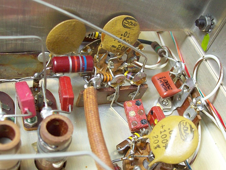
1) RF stage to 6GM6:
- - This change has been made following the original design of the 75A-4. There are some bizarre AVC connections in the mod that replace the original 6DC6 remote-cutoff tube with a 6FV6 which is a sharp-cutoff tube (W2JT, 1962). This circuit have been followed in the same way (copied?) in the K2GL mod to 6GM6 of 1965. These AVC connections involve a large reduction of AVC voltage to the RF tube by means of inserting a voltage divider using 3 or 5 Mohm resistors (this seems quite excessive to me as 6GM6 can handle AVC voltages up to -15 volts).
- - The advantage of the 6GM6 tube over the main problem of the 75A-4 (S-N ratio) is that its high Gm works very well in a low Q circuit (the transconductance of the 6GM6 is more than double the transconductance of the 6DC6). The 6GM6 is a remote-cutoff tube to work in pure broadband circuits, thus low Q. What must be taken into account is that its enormous transconductance implies excellent I-O shielding, but there is no problem here because Collins care a lot on shielding and also due the low Q of the front-end circuit (the fact that the 6GM6 tube adapts so well to the 75A-4 front-end already demonstrates that this circuit is low Q). 6GM6 shares socket connections with 6DC6, no problem here, but since it is a high Gm tube, it has a relatively low internal plate resistance (Ri), thus more mA to plate. As 6DC6 is a 200 VDC tube, and 6GM6 a 125 VDC tube, the original value of the R12 resistor (2K2 ohms) should be increased to 6K8 ohms to save tube life and voltage compatibility. The original 6DC6 screen grid resistor (R11, 33 Kohm) is good for 6GM6, no need to change its value.
- - Strictly following 6GM6 design, a 56 ohm fixed bias cathode resistor would be needed, but I have not placed it following the original 75A-4 design, as the AVC circuit already provides good elbow bias. That's why it is inconsequential to put 3 or 5 Mohm resistors that almost completely eliminates grid bias by AVC voltage, it seems that whoever put those M values believed the phrase "applying AVC to the RF stage deteriorates the noise figure of that stage" (from Collins' note), but that phrase only applies to the ultra-flat Q design of the 75A-4, which is what Collins speaks, and Q is what we have to increase (if bias increases Ri of the tube increases, thus Q at the output tank increases).
- - The result is very good, the signal-to-noise ratio, which is directly related to the Q, of the RF stage is clearly improved. I can highly recommend the change. It only requires replacing V2 with 6GM6 and changing R12 value to 6K8 ohms, 3 watts to adapt plate voltage, see below. New plastic C20 capacitor on the right.
2) Increased IF signal dynamics:
- - Collins does not recommend changing the value of R46, but as the modification table demonstrates, few have heeded the advice (IMO doing the right thing because if not there is no way to improve the S-N ratio of this receiver). Precisely one difference between the 75A-3 and the 75A-4 is that the IF chain in the 75A-3 has more Q (therefore dynamics) than the 75A-4, another difference is that the 75A-3 does not have PASSBAND TUNING. Due to the flat IF response that PASSBAND TUNING requires, perhaps this influences the poor S-N ratio of the 75A-4.
- - It is very important to keep in mind that as more signal dynamics are introduced into the receiver, the AVC of the 75A-4 will become "short" precisely "because of the flat AVC characteristic of the receiver" (text taken from the manual, page 4-4 2nd paragraph, and due "a low impedance AVC line is employed", title 7, AVC system. This will create the need to act on RF gain or increase slow AVC to avoid the usual "pumping".
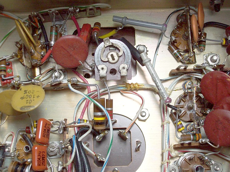
- - Shunting an RF coil with a resistor is an easy way to increase bandwidth in that coil. The resistor kills Q, and kills as much Q as the lower its value. By removing the resistor or increasing its value, Q increases and thus signal dynamics. See below the variable Q setting for L27. The 22 Kohm
shunt resistor R46 is connected in series to a variable resistor of 100 Kohms, this allows a setting ranging from the 75A-4's original setting to a setting where R46 has almost no effect. As you can see, R46 is acted upon in a controlled manner and R29 is not touched (it is in parallel with an RF choke of 2 mH, not a coil), which form an aperiodic design that aims for flat responses... everything is flat on the 75A-4! This approach represents a limited action on the dynamics that does not violate the AVC design too much.
- - Current R46 setting corresponds to a 68 Kohm resistor (22 Kohm of R46 + 46 Kohm of adjusted value in the variable resistor), see below, and note the change from the leaky C81 and C104 micas to tubular ceramics.
3) Increased signal dynamics in the first mixer:
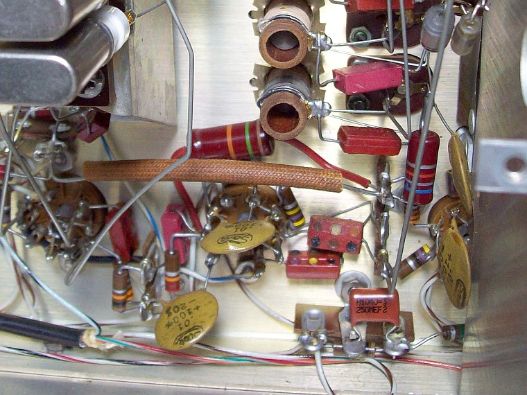
- - The screen resistor value of the first 6BA7 mixing tube (R15) follows the rule of putting low resistance values to give a low Q. The low value chosen here (4K7 ohms) causes even the maximum standard screen voltage for this tube (100 volts) to be exceeded. It is changed to the standard value for that tube (15 Kohms), both to lower the voltage and to increase the transconductance of the plate and thus increase signal dynamics, see below.
4) R86 change to 3 Watts:
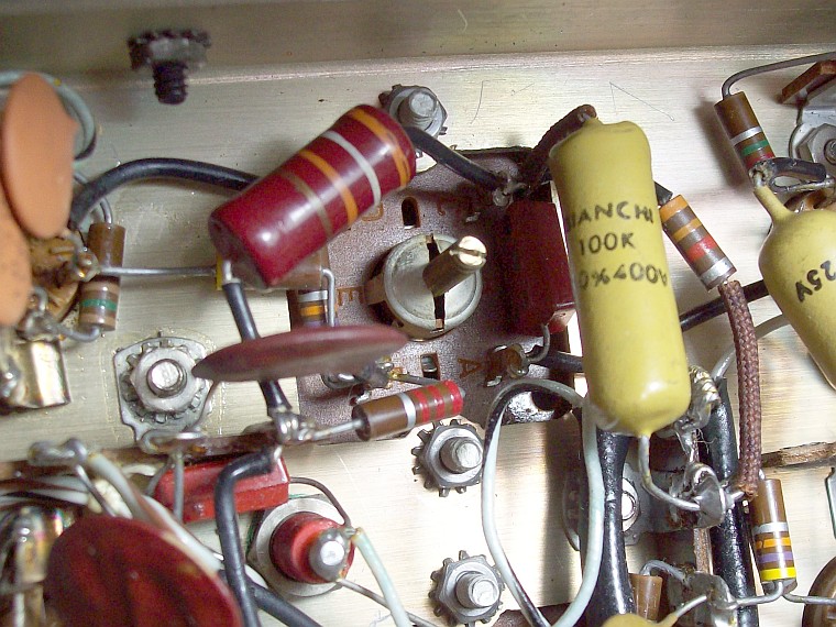
- - The original 39 Kohm 1/2 watt resistor (although the manual says it should be 1 watt) gets considerably hot, not enough to start blackening, but
borderline. An increase in current carrying capacity is strongly recommended. See below a 39 Kohm 3 watt resistor, and mustard-type plastic capacitors replacing Sprague paper ones.
5) R130 is added to create more precise IF threshold control (not included in this particular unit due to its SN).
- - This mod changes a simple voltage configuration in series with the cathode (which causes an equivalent negative bias on the control grid) to a combined application of the same with the addition of some voltage coming from the B+ line through a resistor of 56 Kohm. This allows for more precise adjustment and a more stable cathode voltage. The voltage set at the cathode should be about 4 volts, and the resistor should be minimum 3 watts.
- - See R130 56 Kohm 5 watts on a strip below the shaft. The new circuit to prevent B+ from passing through the mechanical filters already was included at the factory by serial number (on the right), the new orange-drop type plastic capacitor is C62.
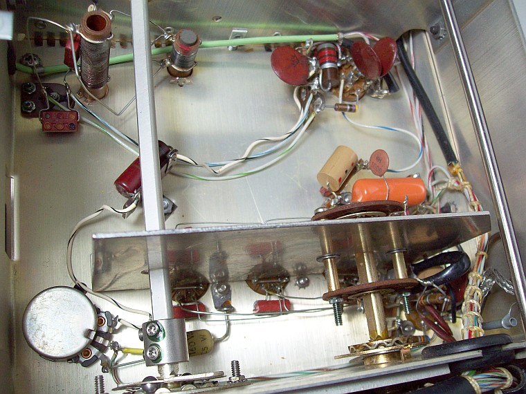
6) Updating the S-Meter circuit to the newest one (not included in this particular unit due to its SN):
- - This mod is made using the original wirewound resistor housings to mount the new potentiometers, thus allowing the original layout of the S-Meter controls on the chassis to be maintained; see 75A-4 main page.
7) Capacitors review:
- - See dedicated page.
8) 1st audio amplifier (V13) from 12AT7 to 12AX7:
- - The component values of the 1st audio amplifier circuit (V13) are the typical for the 12AX7 tube (although 12AT7 can also work with these values). The 51J-5 receiver has an identical audio preamp circuit... but applied to the 12AX7 tube. It seems that the Canadian designer of the 51J-5 also noticed this peculiarity and installed the correct tube. Both are signal tubes; the difference is that the 12AX7 is primarily used for AF, while the 12AT7 is for RF. Therefore, I replaced the 12AT7 V13 with 12AX7 to match the original circuit design, not the circuit implementation.
The 75A-4's underlying trend: 75A-4 has a problem regarding signal-to-noise ratio due its front-end is low Q and the IF chain is designed to handle signals that match a "low impedance AVC line". Low impedance AVC line = short AVC = AVC tubes never will go high impedance = low Q design = wideband = noise. Therefore 75A-4 may not receive any signal that is in the air, but it sure receives any noise coming from the air. |
 |
|