A TV-7 does not have any type of AC filter with electrolytics, so it is not necessary to execute any controlled start-up protocol, it is only necessary to remove the underlying internal ambient moisture typical of these devices. This is achieved by airing it out a bit, and then keeping it plugged in for a while before putting it to use. You can also take the precaution of raising the resistance in series with the transformer by turning LINE ADJUST counterclockwise, which reduces line voltage.
First of all, we can perform a preventive starting procedure including the basic short circuit test as described in the manual.
- Connect the tube tester to a 115 VAC line and set power ON, pilot lamp should light. 115, european users beware!
- Press pushbutton 1 - LINE ADJ and rotate the LINE ADJUST control knob until the
meter pointer rests OVER the LINE TEST mark on the meter face. Release
pushbutton 1.
- Set selectors: left FILAMENT to A, the right FILAMENT to P, GRID to 0 - PLATE to 0, SCREEN to 0, CATHODE to 2, SUPPRESSOR to 2. This means a code-selector AP0-0022, as used on the selectors column on the tube data list.
- Rotate the FUNCTION SWITCH through
the five SHORTS positions.The neon SHORTS lamp should glow in positions
2 and 3 of the FUNCTION SWITCH to indicate that the short test circuit
is functioning properly.
- Set the power switch to OFF position.
After that, we can do an extended test with the intention of checking the voltages under no-load conditions.
- Set FILAMENT VOLTAGE to 0.6, BIAS to 0, FUNCTION SWITCH to A, selectors on HS5-3468.
- Power ON. Presspushbutton 1 - LINE ADJ, the meter pointer must rest over the LINE TEST
of the meter face.
- FILAMENT
VOLTAGE test: Insert leads of a multimeter (AC range) between
pins 2 and 7 of the OCTAL base (count counter-clockwise), a voltage of
about 0.6 should be read, rotate FILAMENT VOLTAGE and check rest of positions,
when 117 is achieved, about 120 VAC
must be read on the multimeter. Note that a 5% of increment is considered
normal on all positions due to the measure is accomplished under no load
condition.
- BIAS
SIGNAL test: Connect leads to pin 6 CATHODE and 5 GRID (count
counter-clockwise), about a 5 VAC must
be read. Setting FUNCTION SWITCH - RANGES on positions B, C, D, E, F respective
readings must be 5, 5, 1, 0.5, 0.5 VAC with BIAS
at 0.
- BIAS
VOLTAGE test: Select DC range on the multimeter, connect the
black lead (negative) to pin 5 GRID and the red lead (positive) to pin
6 CATHODE (count counter-clockwise) in order to measure negative voltage,
set BIAS to 25, a voltage of about 4 volts should be read on the multimeter,
rotate clockwise BIAS to 50 and check if voltage increases about up to
14. Set BIAS to 75 and check if the reading is about 26. Rotate to end
scale at 100 and check if voltage is 40
VDC. Setting RANGE F the BIAS voltage is divided by 10 (0.4
- 1.4 - 2.6 - 4.0 readings on same positions).
Note: measurement contains a combined
AC/DC voltage (AC bias signal to grid + AC ripple in the positive voltage
injected to cathode in order to make the grid negative), a cheap DMM could
give wrong readings due lack of resolution when it attempts "to read" properly
this voltage.
- PLATE
VOLTAGE test: Connect the red lead (positive) to pin 3 PLATE
and the black lead (negative) to pin 6 CATHODE (count counter-clockwise),
press 3 - MUT COND, a voltage of 200 to 210 VDC
should be read on the multimeter with BIAS at 0. Rotate BIAS up
to 100 and check if voltage increases 20 volts. On RANGE F the reading
is always of 220 to 230 volts regardless
the BIAS control position. Beware with cheap DMMs:
the source voltage contains AC ripple, if the reading is unstable and blinks
use a VTVM, a VOM, or a quality DMM.
- HI
SCREEN VOLTAGE test: Move the red lead (positive) to pin 4 SCREEN
(count counter-clockwise), press 3 - MUT COND, a voltage of about
130 VDC should be read on the multimeter with BIAS at 0.
Rotate BIAS up to 100 and check if voltage decreases 40 volts. On RANGE
F the reading is always 130 volts, it's affected minimally by the BIAS
position. The source voltage contains AC ripple, read above.
- LO
SCREEN VOLTAGE test: Connections as above, depress both 3 -
MUT COND and 2 - DIODE pushbuttons, the mutimeter should indicate about
56 VDC with BIAS at 0. Rotate BIAS up to 100 and check if
voltage decreases 40 volts. On RANGE F the reading is always 56 volts,
it's affected minimally by the BIAS position. The source voltage contains
AC ripple, read above.
- ZERO
METER Gm indication test: Connect a 10,000
ohm 2 watt resistor between pins 3 to 6 of the OCTAL test socket
(plate to cathode, remember count counter-clockwise). Depress pushbutton
3 - MUT COND, the meter pointer should indicate 0
±½, otherwise the Gm meter bridge is unbalanced. Power OFF.
Remove resistor.
If all of the above are reasonably OK, you probably have a working unit that only needs marginal adjustments... OR NONE AT ALL if the transconductance/RANGE test described on page 4 is also reasonably good. You can safely test tubes... and in the latter case, make correct evaluations of the tubes being tested.
Tools needed for adjusting: Nothing complicated, an analogic multimeter
(VOM, VTVM) or a quality DMM, a NOS 6L6 tube from a trusted manufacturer
(two or more is best in order to make comparisons), a 330,000 ohm resistor
for the PLATE and SCREEN tests, a 56,000 ohm resistor for the BIAS test,
and a 10,000 ohm 2 watt resistor for adjusting the balance at zero
in the Gm test. For the rest: a 5,600 ohm 6 watt resistor for
the SHUNT test, and the two resistors related below for the SHORT test.
Specific
SHORTS test.
-
Continue with selectors HS5-3468
and the controls BIAS to 0 and SHUNT
to 0.
-
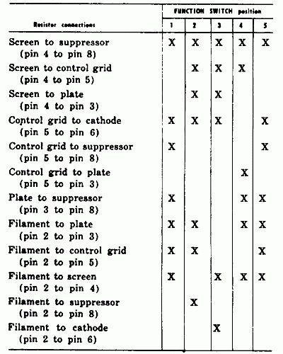
Connect
a 100,000 ohm resistor between the pins of the OCTAL test socket
as indicated in the chart and rotate the FUNCTION SWITCH to positions 1
through 5. The SHORTS lamp should glow in
the positions marked "X" when the above resistor is connected between the
indicated pins on the OCTAL test socket.
-
Connect
a 560,000 ohm resistor between the pins of the OCTAL test socket
as indicated in the chart and rotate the FUNCTION SWITCH to positions 1
through 5. The SHORTS lamp should NOT glow
in any combination of FUNCTION SWITCH position or resistor connection.
|
 |
|


