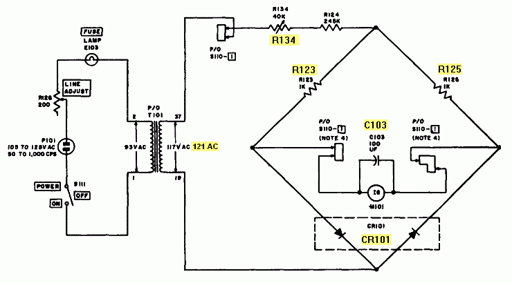
ACV set up and rectifier bridge circuit test.
It is mandatory to reach an agreement among meter
pointer - LINE TEST mark - correct transformer output voltages.This
procedure ensures that all internal voltages have correct values setting
the reference for correct operation. LINE ADJUST regulates the voltage
that determines all voltages in the unit.
-
Set FILAMENT
VOLTAGE to 117, continue with FILAMENT switches to H and S, connect
the multimeter (AC voltage) to pins 2 and 7 of the OCTAL test socket, the
count must be accomplished counter-clockwise on top, easy in this case
because this pins are symmetrical to mount guide.
-
Rotate LINE ADJUST until 121 volts AC exists between filament pins 2 &
7. In the position 117 of the filament switch these pins are connected to terminals 19 and 37
of the secondary of the transformer T101. Check if the voltage across primary,
terminals 1 and 2 (also corresponding to the POWER switch and to the FUSE
socket terminals), is about 95 VAC. This excess of 4 volts compensates
for the effect of the load under test conditions.
-
If the the meter pointer does not match with the LINE TEST mark, the variable
resistor R134 must be adjusted to get LINE
TEST coincidence on the meter when about 121 volts AC exists between filament
pins 2 & 7 with filament switch in position 117 and pushbutton
1 LINE ADJ depressed. This is the most important setting on a TV-7, since all the others depend on it. Tube testers primarily test filament activity, therefore the main reference is filament voltage, not plate voltage.
-
If the coincidence voltage/line-test
is not possible, LINE ADJUST must remain positioned at 121 volts, and a
problem in the rectifier bridge circuit of the meter will be predictable.
-
Check both diodes of the CR101
part using the diode test of a digital multimeter, can be checked directly
in-circuit, observe the forward value obtained in each diode, see the
"new CR101" replacement part for this unit, and this part installed on the appropriate FUNCTION SWITCH lug. New diodes are silicon 1N4001 (this part may be checked by substitution using two 1N4001 to 007 rectifier diodes), but the Weiss & Wise patent of 1955 refers to the originals as germanium 1N91. Full meter deflection is 0.5 volts only, I choose 1N4001 because the lower voltage rating of this diode matches well with this specific use. [The forward resistance and voltage drop in a low voltage diode are usually lower than in a high voltage diode, so in this application 1N4001 will have better efficiency than 1N4007; but I also suspect that the popular 1N4148 small signal diode would also be appropriate... or even an equivalent to the Ge 1N91].
If the LINE TEST point remains unchanged, replacement is not necessary, the original CR101 may be reinstalled to preserve the original design, but perhaps exists a better location for this component that allows to check easily the internal diodes using respective switch connections (see the last pic on the first page).
-
Check if R123
and R125 has both same value, can be checked directly in-circuit
(around 1000 ohms, not specially critical, it is more important to check
if both resistors have matched values, as this ensures balance at zero).
-
Check the 100 µF capacitor
C103 in parallel with the meter, unsolder
one or both ends of this capacitor if the anomaly persists, it acts as
a filter capacitor in parallel with the meter, check value, check if exists
leakage at 10 VDC... if it's leaky, the meter pointer will move slowly
(don't confuse slowly with smoothly) and take a backward position. There
is an easy way to check if exists a problem with this capacitor, unsolder
one end with the intention of disconnecting it from the circuit, the needle
will have a more vivid movement with a forward and backward peak. Note
the static position of the needle, when connecting this capacitor again,
the needle must go to the same position when it was disconnected. In fact,
this capacitor serves to smooth the needle movement, but if it's leaky
can act as a resistor in parallel with the meter. Don't
expect perfection, simply a reasonable value and good functional condition.
Resistors have tolerances up to 20% when new in the year of manufacture,
condensers even greater, circuits were designed to accommodate such variations.
Many amateurs consider this parts are way out due age, this is not always
true and the replacing job is futile. The most critical component in vintage
gear is the paper capacitor, which go bad with aging without being used,
not tubes, or even electrolytic capacitors, but not all capacitors develop
the same process. Replacing components indiscriminately by aging reasons
is in a lot of cases unnecessary.
- There
is an easy way to check the meter: simply unsolder
the red wire and check continuity respecting polarity, choose first a high
ohmic range on the tester to avoid a strong deviation of the needle since
the voltage provided by the tester may be excessive if a low ohmic range
is selected. The tester should give a reading from 2,370 to 2,390 ohms,
including the internal resistor and contact resistances, the meter has an internal resistor
in series with the moving coil, this explains the high ohmic value.
Voltage at end scale is 470 mV in this case, this means 0.470 volts
/ 2,390 ohms = 196.6 µA, close 200 µA, as stated on the meter
face. This voltage can be measured directly on the meter terminals using
a VTVM or a DMM (instrument of high internal resistance). If the reading is greater than
2,370 check if the lug of the spiral holder has a wire welded on it, if not, maybe one of the
rear terminals is not connected to the moving coil but to mass, the adjustable
spiral holder (which has the lug and an extension to the mechanical zero
adjust) is contacting with mass, this feed trough mass contact can become
unsafe due aging and may cause meter does not work or erratic responses.
Alternatively, a meter can work OK but it may have resistance contact: a meter that has an
unsoldered lug and has internal resistance greater than 2,370 ohms
may reveal this issue; but a shift of 20 ohms with regard to 2,370
is not a problem anyway, the problem is an unsafe contact. To check (and
perhaps to fix up), retouch with a screwdriver the mechanical zero adjust
in order to scrubbing a bit surface contacts. When troubles with meter reading
arises CR101 appears as first candidate, but often the issue is due to the inclusion
of a series resistance in the circuit (which may be inside this sealed instrument,
especially when the set has been unused for many years). The evidence of a spiral
lug unsoldered is the clue for consider to check the meter first instead CR101.
A meter-mark/mV interrelation example: Meter of 2,370 ohms internal resistance.
| mark |
10 |
20 |
30 |
40 |
50 |
60 |
70 |
80 |
90 |
100 |
110 |
120 |
| mV |
40 |
80 |
119 |
157 |
195 |
235 |
272 |
310 |
350 |
387 |
425 |
465 |
The LINE ADJUST circuit: ALL TESTS made with a TV-7 depend on the proper adjust and operation of this circuit.
|
Accurate filament voltage test and adjustment. Filament is the most
critical part in a tube, a significative error is lethal, other
errors are managed very well by the tubes.
-
Set FILAMENT
VOLTAGE to 117, continue with FILAMENT switches to H and S, connect
the multimeter (AC voltage) to 2 & 7 pins of the OCTAL test socket
(count counter-clockwise on top).
-
Rotate
LINE ADJUST until 117 volts AC exists between filament pins 2 & 7
(usually one scale division backwards LINE TEST). As stated above, on the
117 position these pins are connected to terminals 19 and 37 of the secondary
of the transformer T101. Check if the voltage across primary, terminals
1 and 2 (also corresponding to POWER switch terminal and FUSE socket terminal),
is about 93 VAC. This assures a well balanced input-output working condition
of the transformer.
-
Set the FILAMENT VOLTAGE switch
to previous step (75), and check voltage on the multimeter, continue with
the same procedure on all previous steps until .6 is reached. In some positions
the reading is exact and in others may have differences, don't worry, that
is considered normal. If the reading differs more than 10% nominal voltage
arbitrate R134 to the best setting for all in order to create a
new LINE TEST indication for to compensate voltage variations, but this
affects to the adjust related above of course. A significant higher difference
could indicate a problem in the transformer.
ACV signal test. The signal voltage is used on the transconductance test.
It is obtained from the secondary no. 3 of T101 and involves the resistors R120, R121, R122
in series wich acts as a voltage divider depending on the FUNCTION SWITCH
- RANGES selection.
-
Set selectors to HS5-3481,
BIAS to 0, and FUNCTION SWITCH - RANGES to B. Meter pointer must
rest over LINE TEST when LINE ADJ is depressed.
-
Connect the multimeter (AC voltage)
to 5 & 8 pins of the OCTAL test socket (cathode to control grid, remember
count counter-clockwise on top). In the selected RANGE B the multimeter should
indicate about 5 volts.
-
Setting RANGES to C the same reading
as above (5 volts) should be obtained.
-
Setting RANGES to D, the multimeter
should indicate about 1 volt.
-
Setting RANGES to E, the multimeter
should indicate about 0.5 volt.
-
Setting RANGES to F the same reading
as above (0.5 volt) should be obtained.
|


