Preliminary
considerations: A quality digital or analogic
multimeter may be used. I recommend a classic VTVM (common to cathode connection).
DCV is unfiltered, a cheap DMM could give an erratic voltage indication
due the presence of AC ripple. The effective load applied by the multimeter
to the circuit is from low to very low in all cases. About this matter
I think there has been spread some confusion, the multimeter
TS-352/U mentioned in the manual has 2.5 - 10 - 50 - 250
- 500 - 1000 volt input jacks with two selectable sensitivities on DC:
20 Kohm/V or 1 Kohm/V; on AC is 1 Kohm/V only. Despite
that the DC 20 Kohm/V range was available... "surprisingly" only the 1
Kohm/V range was used... WHY?... because an
effective load beyond 100,000 ohms is negliglible!!! The
250 volt jack implies a load of 250,000 ohms under 1 Kohm/V,
and combined with the 375,000 ohm resistor the effective load is 150,000
ohms... then, no problem. Nowadays, using a high resistance multimeter,
a load resistor of 56 Kohm would be needed considering the use of the 50
volt jack for the bias adjust to 40 volts
since the use of the 250 volt scale would not be enough accurate, the TS-352
load is 50,000 ohms in this case, but the shunt effect combined
with the 3,000 ohm BIAS potentiometer is only clearly noticeable beyond
halfway of this control, and this margin is the least used. Using the 10
volt jack the load is 10,000 ohms, the bias voltage cannot be adjusted
correctly using several scales due the load changes, it is contradictory.
And as the AC range is only used for testing transformer output voltages
like filament (low resistance source) no problem at all. A compensating
shunt resistor is not needed on measuring, the only required is the standard load
resistor (an extra load resistor of 56 Kohm is needed for bias adjustment if a high resistance multimeter is used), but neither an exact value is needed and
nor it is always required.
Unlike
as described in the Field and Depot Maintenance manual, all the procedures
shown here and in the next paragraphs are based on the 6L6 tube settings.
NO special adjusting gear, nor "adjusted" calibration tubes required!!!
- Set controls: BIAS to 23, SHUNT to 0.
- Set selectors: FILAMENT VOLTAGE to 6.3, pin switches to HS5-3481, RANGES to D.
|
PLATE VOLTAGE
check. The plate testing voltage is fixed at about 150
volts, and this voltage is provided by the 83 tube and may vary by the
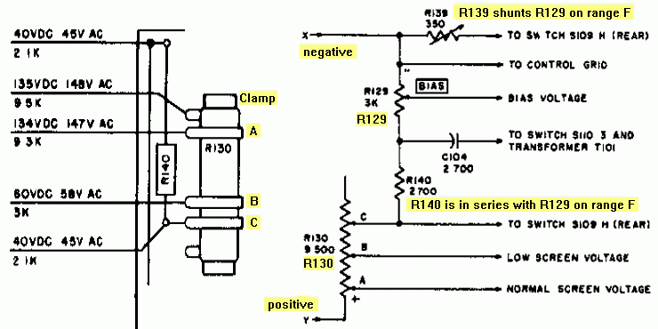
influence of the voltage divider (see schematic below). When a rectifier
tube is tested, a different circuit is connected and plate voltages may
vary depending on the pushbuttons DIODE, OZ4, and RECT. On this case these
voltages are not originated by the 83 tube, but by the secondary of the
T101 transformer, and they are applied to the SAME tube that is being tested.
Before proceeding, the meter must rest over the mark LINE TEST when pushbutton
LINE ADJ is depressed.
- Connect
a 330,000 ohm resistor (manual says 375,000 but don't worry about
exact value, beyond 100,000 ohms the effective load is negligible) between
pins 3 to 8 of the OCTAL test socket (plate to cathode, remember count
counter-clockwise on top).
-
Connect the positive lead of
the multimeter (DCV) to pin 3 and negative to pin 8.
- Depress the pushbutton 3 - MUT
COND, the multimeter should indicate about 150
volts (± 3). If there is noticeable difference, a problem
in the power supply should be suspected. Note: this voltage is affected
by the AC ripple of the DC voltage, a cheap DMM could give wrong readings
on this due it could not "read" properly the amount of DC voltage.
BIAS VOLTAGE
check and adjustment. The bias voltage is the negative
voltage applied to control grid of the tube to be tested. This voltage
is regulated by means of the BIAS control, and it is provided through of
a voltage divider associated to the 5Y3GTA rectifier (see schematic below).
Note: this voltage will be increasingly affected by the AC ripple of the
DC voltage when the BIAS control is being rotated up to 100, a cheap DMM
could give wrong readings on this due it could not "select" properly the
bias voltage. Before proceeding, the meter pointer
must rest over the mark LINE TEST when pushbutton LINE ADJ is depressed.
- Connect
a 56,000 ohm resistor (if a VTVM or a DMM is used) between pins
5 to 8 of the OCTAL test socket (control grid to cathode, remember count
counter-clockwise on top).
- Connect the negative lead of
the multimeter (DC) to pin 5 and positive to pin 8 of the OCTAL test socket.
- With the BIAS control to
23 the multimeter should indicate about 3.4 volts (±
0.2).
- Adjust the BIAS control to
50, the multimeter should indicate about 13.4
volts.
-
Adjust the BIAS control to
75, the multimeter should indicate about 25.8 volts.
-
Adjust the BIAS control to
100, the multimeter should indicate about 40
volts. But then don't be obsessed on getting 40 volts at 100,
it's better to do the fine adjust to 50, halfway, since 0 to 50 is the most
used margin.
- If the measured voltages differs
substantially adjust clamp C of R130 (see
figure below) until the correct voltage is obtained. Alternatively, arbitrate
the position of clamp C until these voltages were approximately measured.
- Maintaining the BIAS control
to 100 and setting RANGE F the multimeter should indicate 4
volts. This is caused by the action of the variable resistor
R139 (see below) wich is connected in parallel with R129 (the BIAS control),
and R140 is connected in series with this control. The addition of R139
and R140 reduces the current through the voltage divider affecting seriously
to R129, and in a lesser extent to R130. If the voltage differs substantially,
adjust R139 until 4 volts are obtained.
This range is in fact a sub-range of range E. At mark 100, maximum bias is -4, not -40 as in the previous ranges (B, C, D, E), thus it allows a precise bias adjustment (or less prone to errors/tolerances) in low voltage bias tube tests. VERY FEW tubes test in this range, so it seems that RANGE F is an unterminated project.
HI-LO SCREEN GRID VOLTAGE
check and adjustment. Normal screen voltage is
130 VDC. If his voltage is too high for the tube under test, a lower screen
grid voltage of about 56 VDC can be applied by depressing the DIODE pushbutton.
Before
proceeding, the meter must rest over the mark LINE TEST when pushbutton
LINE ADJ is depressed. The BIAS control
must be positioned at 0, unlike plate
voltage, the screen voltage is strongly affected by the BIAS position,
with BIAS at 100 the voltage decreases 40 volts exceptuating on RANGE F
where only decreases 5 volts, see schematic above. Note: this voltage
is affected by the AC ripple of the DC voltage, a cheap DMM could give
wrong readings on this due it could not properly "read" the amount of DC
voltage.
- Connect
the 330,000 ohm resistor... or nothing
as the shunt effect is very low (see schematic above), between pins 4 to
8 of the OCTAL test socket (screen grid to cathode, remember count counter-clockwise
on top).
- Connect the positive lead of
the multimeter (DC) to pin 4 and negative to pin 8.
- Depress the pushbutton 3 - MUT
COND, the multimeter should indicate about 130
volts (± 3) with BIAS at 0.
-
High
screen adjust: If the multimeter does not indicate 130 volts
(± 3), adjust clamp A of R130 until
the correct voltage is obtained.
- Depress BOTH the 3 - MUT COND
and 2 - DIODE pushbuttons, the multimeter should indicate about
56 volts (± 1,5) with BIAS at 0.
- Low
screen adjust: If the multimeter does not indicate 56 volts
(± 1.5), adjust clamp B of R130 until
the correct voltage is obtained.
- If the difference between the
plate voltage (150 ± 3) and the high screen voltage (130 ±
3) is excessively greater than 30 volts or less than 10 volts a problem
in the divider or in the power supply should be suspected.
|