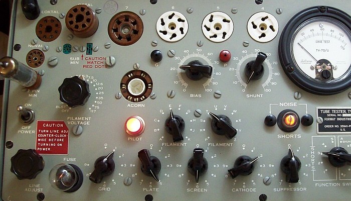
Bear in mind that the most reliable tests that can be performed with any TV-7 are transconductance tests related to amplifier tubes (triodes, pentodes, etc.), and emission tests related to diodes and rectifier tubes. All other tests do not guarantee absolute accuracy, it is VERY important to remember this to avoid accidentally discarding properly functioning tubes.
VR tubes are tested in a very unprofessional way using AC voltage as if they were rectifier tubes, much like NEON LAMPS! Because of this, I don't recommend testing VR tubes on a TV-7.
Rectifier tubes are tested using several AC voltages from the secondary of the power transformer.
If a step-down transformer is used (e.g. 230/115), it's strongly recommended that it provides an output
of 115 VAC as accurate as possible, in order to avoid an excessive overload to the LINE ADJUST rheostat.
CAUTION: Do not insert a tube into a test socket until all of the controls (mainly filament switches) have been set in accordance to the instructions listed in the Test Data Manual.
To avoid unrecoverable errors NEVER ASSIGN other FILAMENT connections with a tube plugged in and the TV-7 turned on. Set filament voltage with no tube in the corresponding socket, and after plugging one in, run the LINE TEST again as filament amperage affects the setting of the TV-7. However, when a multi-section tube is being tested, new connections can be assigned with that tube in the socket. In addition, several tubes of the same type (name) can be tested on the fly by removing the existing tube and inserting another one; but in this case it must be taken into account that the tube to be removed could be very HOT!
Ideal sequence of test steps based on tube type or section type:
1) The SHORTS and GAS tests are highly recommended but may be relegated to optional due to inconsistencies (info about this on several pages ahead).
2) Emission and transconductance tests are usually very reliable.
3) All other tests may be questionable (special tube-types) or avoidable/harmful (VR tubes).
Full step to step operation (it may be summarized):
Locate the type number of the tube to be tested in the "Tube type" column
on the settings page.
Turn the FILAMENT VOLTAGE knob to the position shown in the "Fil" column
on the settings page for that specific number tube.
Set the selectors to the letters and the numbers indicated in the "Selectors"
column on the settings page. Be sure that the numbers indicated by the
selector knobs are the same, if read left to right, as the numbers in the
column for that specific tube number in the settings data.
Set the BIAS control to the number indicated in the "Bias" column of the
settings data for that tube number.
Set the SHUNT control to the number indicated in the "Shunt" column for
that tube. If there is no settings number listed in that column, then disregard
this step and proceed with the steps below.
Set the FUNCTION SWITCH knob to SHORTS 1.
Insert the tube to be tested in the proper socket and, if the instructions
in the "Notations" column require it, connect panel jacks G or P to the
tube caps with the test leads.
Set the POWER switch to the ON position. The PILOT lamp should light. Note:
For tubes of the heater cathode type, allow approximately 2 minutes for
the cathode to reach operating temperature before you test the tube.
Press pushbutton 1 - LINE ADJ and rotate the LINE ADJUST knob until the
meter pointer rests OVER the LINE TEST mark on the meter face. Release
pushbutton 1. This must be always done in order to prepare the set for each
tube to be tested as each tube loads the set with more/less filament amperage.
Note: Some tubes require that the meter pointer be set at a position other than
the LINE TEST mark. Refer to the "Notations" column of the settings data
before testing the tube.
If you don't want to perform the SHORTS or/and GAS tests, you can go directly to : MAIN TUBE TESTS (Gm or Emission).
Start standard testing procedures with the optional SHORTS TEST. This test is highly
recommended when testing a totally unknown tube because it can prevent damage to the set... BUT this test may give false positives when testing some types of high transconductance tubes. A complete warm-up of the set is recommended before performing the shorts test.
Turn the FUNCTION SWITCH knob from SHORTS 1 to 5 and tap the tube lightly watching
the SHORTS lamp on each switch position. Tubes with shorted elements will
cause the lamp to glow. Note: Some tubes can be permanently damaged
by tapping on them while testing, check the "Notations" column.
A short is indicated by a steady glow of both halves of the SHORTS lamp. A flash
when the switch is turned from one position to another does not indicate
a defective tube. Intermittent flashing when the tube is tapped is
an indication of the existence of loose elements which can cause noisy
or erratic operation.
Tubes that have more than one section must be tested for shorts on each section.
Discard a shorted tube without further tests. Ignoring this can damage the
tester meter or other parts... BUT some tubes will show a shorted
condition on certain positions of the FUNCTION SWITCH even though they
are good tubes, also check the "Notations" column in the settings data for that tube to remarks.
Combinations of lamp brightness that all together indicate a kind of short.
Kind of short
FUNCTION SWITCH position
1
2
3
4
5
Filament to Cathode (cathode leak), see example below.
X
Filament to Plate
X
X
X
X
Screen to Suppressor (or several elements shorted)
X
X
X
X
X
Cathode to Control Grid (grid leak, indirect heating)
X
X
X
X
Control Grid to Plate
X
Filament to Control Grid (grid leak, direct heating)
X
X
X
Control Grid to Screen
X
X
X
Control Grid to Suppressor
X
X
Screen to Plate
X
X
Supressor to Plate
X
X
X
Filament to Suppressor
X
Filament to Screen
X
X
X
X
X = The lamp shines. Multisection tubes must be tested for shorts by individual sections.
Optional
GAS TEST but recommended test. The gas test DOES NOT apply to DIODE sections or RECTIFIER tubes. Allow tubes of the filament type to warm up before testing the tube for gas content. This test may give surprising results when testing some types of high transconductance tubes.
IMPORTANT!!! DO NOT TEST cold cathode VR tubes with TV-7s. Cold cathode VR tubes are 0A2, 0B2, etc... The chance of damaging them is HIGH! Consult TV-7 test methods explained. A damaged VR tube by a TV-7 can be recovered, but it's much better to avoid the procedure.
Pushbutton 4 - GAS 1 and pushbutton 5 - GAS 2 are used when
testing amplifier tubes for gas content. Multipurpose tubes are tested
for gas content only on the amplifier sections.
Set the controls as indicated in the settings data for the tube under test.
In order to perform an accurate gas test, a complete warm-up of the set may be needed.
Press pushbutton 1 - LINE ADJ, if the meter point does not rest over LINE TEST
correct this rotating LINE ADJUST. Release pushbutton 1.
Hold down pushbutton 4 - GAS 1 and adjust the BIAS control until the meter pointer
reads 10 on the scale.
Note: If the meter pointer cannot be adjusted
down to 10, turn the BIAS control knob until the meter reading is 100.
Hold down pushbutton 4 - GAS 1 and press pushbutton 5 - GAS 2.
If the tube contains gas, the meter pointer will move upwards on the scale. A
movement of more than 1 division of the scale for a normal transconductance
tube like the 6L6 (6 mA/V of S under class A operation) indicates
a gassy tube, BUT if the tube tested is a high transconductance tube like
EL84 (11,3 mA/V of S under class A operation) the gas test may be inconclusive,
see "The peculiar EL84 case" (mouseover the link with that title above).
MAIN TUBE TESTS: If the tube is not shorted or does not contain gas, the TRANSCONDUCTANCE TEST (signal-amplifier tubes), or the EMISSION TEST (rectifier/diode tubes), can be performed safely.
Set the controls as indicated in the settings data for the tube under test. The FUNCTION SWITCH pointing the RANGES position indicated in the "Range" column of the settings data automatically sets the sensitivity of the meter circuit to the proper level for the tube under test.
Refer to the "Notations" column for specific information pertaining to specific tube types.
Look carefully at the button you have to press to do the test. IMPORTANT!!!DO NOT PRESS pushbutton 3 - MUT COND⚠ by mistake (or routinely) when/while testing DIODE or RECTIFIER tubes since the meter pointer will move sharply to the far right, and the FUSE lamp will react indicating an overload. A pushbutton safety cap (see pic on the right) is a handy solution to avoid pressing MUT COND by mistake when testing diodes (PB 2), or inattention when testing rectifiers (PB 7), and voltage regulator tubes (PB 4) (BTW, don't test VR tubes with a TV-7). Covering the #3 MUT COND pushbutton with something protective should be the first action when testing DIODE or RECTIFIER tubes.
Press the pushbutton indicated in the "Press" column of the settings data for the tube being tested. CAUTION: Release the pushbutton as soon as the meter pointer comes to rest and the meter indication is read. If the pushbutton is held depressed too long, the tube under test may be damaged.
When the correct pushbutton is depressed, the meter will indicate the condition
of the tube. Compare the meter reading to the value indicated in the "Minimum
Value" column of the settings data for that tube.
If you are careful, there is no need to turn off the set to check another tube. Remove first the tested tube (watch out! it's HOT), re-set setup switches, re-check the setup (you ALWAYS have to do it) paying close attention to FILAMENT VOLTAGE selection, and insert the next tube to be tested.
The IMPORTANT, though questionable, SHORTS TEST.
Operating principle:
The SHORTS TEST involves selecting 93 VAC from the power transformer and then using a 0.1 µF capacitor as a "resistor" in series with a neon lamp to apply the resulting voltage to the tube pins connected to the electrodes under test. Note that this "resistor" only allows alternating current to pass through. The capacitive reactance in series of a 0.1 µF capacitor at 50/60 Hz is about 30,000 ohms, making this a "high impedance" test compared to the other tests (see schematic on the TV-7 test methods explained page).
SHORTS lamp ON at #3: 6AQ5 tube test: There is a certain level of short circuit between filament and cathode.
SHORTS testing features:
Depending on the voltage level applied to the neon lamp (SHORTS lamp), a short circuit is considered to exist or not.
This 'short circuit' is (usually) due to a 'connection under leaky conditions', not a direct cross-connection.
When the SHORTS lamp is glowing, it means that the crossed leakage exceeds a certain limit, at which point it turns on.
When the SHORTS lamp is turned on, it indicates that the resistance value between the pins of the selected electrodes is less than about 100,000 ohms.
The combination of tube pins selected is given by the position of the SHORTS switch (1, 2, 3, 4, 5).
The AC leakage to the neon lamp (SHORTS lamp) may only be evident when the filament is glowing (tube is HOT; therefore, some dilation exists). When it is not glowing, the short circuit between electrodes may be practically nonexistent, undetectable when testing the tube's pins with an ohmmeter.
Therefore, most of the time, the inter-electrode leakage condition occurs when the tube is in operation; this makes it difficult to clearly identify a SHORTS issue.
Regarding the previous paragraph, one way to detect inter-electrode leakage during the transconductance test is to hold down the MUT COND pushbutton for a few seconds. If the needle remains stationary or only moves back slightly, there is no leakage condition (inter-electrode short). However, if the needle moves slowly and continuously backward, the leakage condition becomes evident in the transconductance test itself (although this can also provide evidence of a very depleted tube). Paradoxically, if the SHORTS test is performed afterward, it may show that no leakage condition exists.
Marginal and Speculative tests
Optional NOISE TEST. This is a very marginal test, only for special checking.
This test needs sound amplification; listening noise with headphones would indicate a real disaster inside a tube (shorts test should already evidence this).
The Noise test jacks on either side of the SHORTS lamp
are used when testing tubes for noise. Best use a radio receiver or an audio amplifier
to perform it. A set of test leads are required to perform the test.
Set the controls for the tube under test as indicated in the test data book.
Set the FUNCTION SWITCH to SHORTS 1.
Connect the test lead from the left-hand NOISE jack to the chassis of the radio
receiver or the audio amplifier.
Connect the test lead from the right-hand NOISE jack to either the antenna of a
radio receiver or the input of an audio amplifier.
Tap the tube under test while the FUNCTION SWITCH is turned from position 1 through
position 5. Intermitent disturbances within the tube which are too brief
to register on the SHORTS lamp will be reproduced as static by the loudspeaker
of the radio or the audio amplifier.
Speculative "LIFE EXPECTANCY" and "REJUVENATION" tests. By default, the tubes manufactured at the time when their use was normal (therefore manufactured under agreed common standards) were prepared to withstand filament voltage changes of up to ±10% nominal. That is, a tube designed for 6.3 volts of filament voltage, can be pushed to 6.9 up, or 5.7 down, without its characteristics being affected. But as it gets older, this statement, which is true when new, ceases to be so with aging.
The "life expectancy" test consists of checking filament activity at the low tolerance limit (5.7), and then verify that the performance margin is already beginning to be affected by the emission of the filament. In case of the TV-7, a transconductance test could be done by selecting the scale lower than 6.3, which is 5 (it might be too low), or doing the test even more incorrectly by lowering LINE ADJUST to obtain 5.7 volts in the filament (this also affects plate voltage) (To be correct, the test must be carried out at the OFFICIAL plate voltage with which, among other parameters, the transconductance value is obtained). The TV-7 is not very well suited to this speculative test, so... "things" to play with.
The "rejuvenation" test CAN be done with a TV-7, and consists of the opposite; make the tube filament work beyond the upper limit, and well beyond, in order to obtain a reactivation of the electron-producing material (strontium, barium, thorium). As an example, it could start with 7.5 volts for 10 minutes, then test the tube; depending on the effect, select 10 volts for 6 minutes, the absolute max will be 12.6 volts (wich is double) for 2 or 3 minutes (again, "things" to play with). Increasing voltage, decreasing time is the safe method for the filament. Temperature is what mainly activates the material, the purpose is that once the filament is activated it lasts. It works, especially when applied to tubes that have performed within specifications, but it's hard to know FROM when and UNTIL when, it depends on how the overvoltage activates the material. In a tube that has already worked hard during its life, nothing, or almost, will be achieved.