About TV-7 use.
- For correct cabinet closure, the PLATE control switch should not be on position 9, and the SCREEN control switch should not be on positions 1, 2, or 3. This is mandatory in order to avoid the knobs collide with the upper data book ring, allowing this manner a correct closing of the cabinet.
- Testing used tubes with dirty pins will cause contact
resistances and insufficient filament heating, consequently bad readings.
- If the meter needle goes back some meter division/s when pressing the test button, this usually indicates that a "tired" tube is being tested (poor filament electron flow). This is especially true when testing rectifier tubes.
- And something well known that always has to be remembered: When testing RF tubes in a tube tester, the performed test is never conclusive since it is being done at line frequency (50 or 60 cs in a TV-7), at much higher frequency a tube has different behavior. Also, the tube under investigation is never going to reach actual-circuit operating voltages, and the same will occur with temperature, so some issues may NOT be detected until operational voltage and temperature are reached, that is, only when the tube operates in-circuit.
- As per tube data list recommendation, the meter indication for tube types such as pentagrid converters, mixers, tyratrons, and voltage regulators [see below], is not a true and conclusive measurement of the tube condition and value. It may be necessary to substitute a known good tube of the same type to obtain a true indication of the tube's condition. I add to these recommendations that the manufacturing characteristics of some high transconductance tubes may not suit the test procedure performed by a TV-7. Do not automatically rule out any of those tube types due to poor test results on a TV-7.
- TV-7 is a direct heir to the WWII I-177 model, which was designed before the development of 9-pin Hi-Gm tubes for TV IF and VHF-UHF frequencies (1950-60). These frequencies imply short/direct internal/external connections, therefore an unique electrode could have more than one connection pin; and on the other hand, a high Gm tube may develop more voltage drop than a regular tube across the grid resistor (R128, 180 Kohm) when it is inserted depressing the pushbutton GAS 2, thereby reducing bias and increasing plate current (it could also be interpreted as a short in the grid). A noticeable increment of plate current is interpreted by the TV-7 as gas; this effect occurs when testing all tubes, but with high transconductance tubes the effect is more noticeable. Therefore, some popular Hi-Gm tubes can give false positives on gas and shorts tests; preventively, these tests must be performed only after a complete warm-up of the set. It seems this behavior of high transconductance tubes was taken into account when range F was included in the model "D", selecting this subrange, a lower value resistor (R141, 47 Kohm) is connected parallel to R128, that is the grid resistor inserted when the GAS 2 pushbutton is being pressed.
[The value of this resistor can be checked this way: power off, insert an ohmmeter between cathode and grid using the number of pins indicated on respective switches, BIAS to 0, depress GAS 2, the reading must be about 38 Kohms on RANGE F, and about 180 Kohms on the rest of ranges. And besides that, the inclusion of ferrite beads in TV-7D/U sockets in order to prevent parasitic oscillation was already in the direction of adapting the set to high transconductance tubes.]
- Watch over when testing a VOLTAGE REGULATOR tube since it can result damaged, TV-7 uses AC voltage for testing VR tubes... a TV-7 tests VR tubes as if they were simple NEON LAMPS!!! When a VR tube is being tested, a very low measurement (even a recoil of the needle) can indicate a bad test, NOT a bad tube; and a strong upper value may indicate also a bad test and NOT a good tube. Stop immediately VR tube tests when the meter shows strange reading behaviors due these tubes may result damaged!!! When damaged, they call for a re-ionization during hours in a separate circuit trying to recover voltage regulation level and tube behavior, but when restored, the current performance will be same as a used VR tube. Testing VR tubes using a TV-7 is a risk procedure, definitively I do not recommend testing VR tubes with a TV-7!!!
[The best way to test VR tubes is in-circuit triggering variations of at least 10 volts at the input of the regulated circuit (the point before to the limiting resistor in series with the VR tube), and at the same time measuring voltage variations at the regulated point (voltmeter in parallel with the VR tube). The best tube is that gives smallest variations at output. Testing a VR tube of same type that is being used in a receiver is very easy: Tune near a very strong signal, connect voltmeter in parallel with the VR tube, then tune to maximum and detune after; the AGC line will cause voltage variations in the B+ line (input of the regulating circuit), then measure VR tube poles and this will show the range of regulation regarding variations at input. A test was made using this method with several 0A2 tubes (new and used); variations from 0.1 volts (excellent regulation for SSB), to 5.8 volts (totally unusable) were found.]
-
The peculiar EL84 (6BQ5) case:
|
GAS!
Manual's definition about the existence of gas (more than one scale division) is not
correct for this tube, all NOS EL84 tests a gas indication of about 5 scale
divisions (10 units). A gassy tube may have a blue glow INSIDE the tube
with high voltage applied (just behind the glass surface is normal), but
here the voltage applied is 150 volts only! ... a visual test is impossible.
Existence of gas inside a tube causes increased resting plate current,
so a gassy EL84 could give optimistic results in a TV-7.
SHORTS!
Similarly occurs with the shorts test. A good EL84 will show the SHORTS lamp glowing in various positions that all
together configure the "lights combination" corresponding to a "cathode to
control-grid" short (neon lamp glowing in FUNCTION switch positions 5-3-2-1).
 EL84 (6BQ5) had no "official" changes since first manufacture, thus the TV-7 does not consider any. As consequence of accommodative changes by manufacturers, the usual EL84 pin layout is not accurate, the vast majority of EL84s have additional access to control grid via pin 1 (see EL84 updated base on the right). But this doesn't end here, some manufacturers, such as Haltron, also add extra access to screen grid via pin 6. The pin 1 undocumented mfg change is the cause of the EL84/TV-7's shorts and gas issues. Logically, the standard TV-7 test refers to pin 2 as the control grid considering pin 1 to be an open circuit. TV-7 tests assume that if a pin is not selected by the corresponding switch position, its internal connection (if any) is out of test. In practice this may be false, some "unused" pins may remain in the test even though TV-7 considers them out of test. If the tube base has pin connections not documented when that tube was included in the test data list, these pins may interfere with the test; but it also happens that when there is a known interference, some "side effects" are considered "normal" in the test data list.
EL84's control grid is mounted between two bars that space and distribute the grid wire. Pin 1 connects to the grid on the opposite side that pin 2 connects, this usually means a distribution dedicated to use in high frequency circuits. EL84s that have additional screen grid connection to pin 6 are not a problem, pin 6 does not cause issues with TV-7.
 There are two solutions to the EL84 problem. There are two solutions to the EL84 problem.
- First the "legal" solution: Do the test without pin 1 in the circuit. For this, the test must be carried out through an interface that eliminates the connection of pin 1. See on the right (and mouse over) said interface using a modified socket saver. Using it, a EL84 can be perfectly tested without mysterious gas or shorts issues.
- Second, the "practical" solution: Since there is an internal connection from pin 2 to 1, consider pin 1 as the "legal" one to do the test (GRID switch at 1). Using pin 1 you can check a EL84 without "side effects" (or so it seems). The internal difference between position 2 and 1 is that on position 2 there is a connection exception in the group A of the GRID switch.
For all that, beware with throwing away a good EL84 (6BQ5) due to bad results on gas and short tests!!! The TV-7 test data book is not fully up to date on high transconductance tubes, and the set is not fully prepared to test these type of tubes. |
-
The peculiar 12AX7 (ECC83) and 12AT7 (ECC81) cases:
EXHAUSTED! It's common to experience a low-reading "surprise" with many tubes of those two types. As stated in the transconductance test page, these tubes can become overloaded very easily. When a faulty test is suspected, the only way to know if those tubes are good or bad is to test them in a different environment; that is, with another tube tester (but perhaps it's best to avoid Hickok-type tube testers), or while they're working online. I test them in a Collins 75A-4 receiver by replacing the 12AT7 audio preamplifier tube. In fact, according to the circuit values, this tube should be a 12AX7 and not a 12AT7; therefore, both 12AX7 and 12AT7 tubes can be accurately tested in the same socket. This test is simple because the cover of the 75A-4 receiver allows it. If the replacement does not produce a significant change, the dubious tube can be considered good. Conclusion: with the current setup, TV-7 cannot test these two tubes homogeneously and efficiently. To achieve this, these two tubes should be tested in the D or E ranges (signal test is 1 VAC and 0.5 VAC respectively), but to do so, all the test parameters for 12AX7 and 12AT7 tubes should be redesigned.
Therefore, and again, beware with throwing away good 12AX7 (ECC83) and 12AT7 (ECC81) tubes due to bad results on the transconductance test!!! The TV-7 test data parameters are not correct for these tubes although in many cases they give correct results. The test procedure needs to be redesigned in order to perform a reliable test with those two tubes.
TV-7 meter operation.
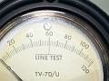
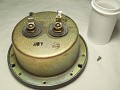
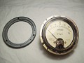
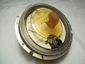
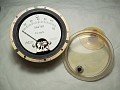
- Latest Phaostron meters (front cover in plastic, not glass) may have a bizarre issue (1) and a very annoying fault (2).
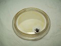
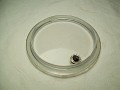
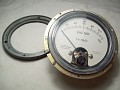
- A sticky, oily yellowish substance on the back of the meter dial cover that collects on the sides and looks like internal moisture. The plastic cover must be removed and the substance diluted in alcohol, then washed with a mild (e.g. dish) detergent. This goo comes from the type of rubber that was used, as it ages it "sweats"; the same goes for the rubber caps on the E105 adapter cables (3E29, 829-B, 832-A tubes).
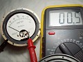
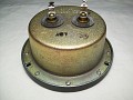
- A contact fault between ground and the front spiral due to aging. The negative terminal on the back is not soldered to the lug of the front spiral, but is in contact with the ground of the instrument and, by surface contact, the current passes through the spiral to the moving coil of the instrument. When ground and spiral contact loses quality, a certain resistance value is added in series with the meter, this may cause continuity to fail partially (it can cause low readings on all scales, or a wrong initial setup, detectable by the intense glow of the pilot light), or a complete meter failure if too much series resistance is added.
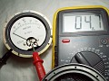
- Pics below show how to fix the goo issue, and prove that the resistance value from the negative terminal on the back to the lug of the spiral is not the same as the negative terminal on the back to the ground of the instrument (virtually zero, only contact value). A possible solution to avoid this is shunting the surface contact by connecting the lug of the spiral to one of the two side screws.
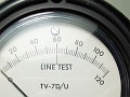
- In order to protect the TV-7 meter, there is a very widespread legend that comes from a correct idea but also from a misunderstanding. Some VOM manufacturers added opposing diodes in parallel to the instruments to protect them from overloads. The idea is that silicon diodes need a minimum forward bias voltage (contact potential) of 0.7 volts (typically), and since the TV-7 meter has full scale reading at 0.5 volts (it may vary a bit), any circulating current should not cause conduction in a shunt diode located at forward current. So within this non-conduction range, the meter would not acknowledge any presence of a diode. But the usual thing is that a diode progressively enters conduction as it approaches the conduction threshold, this will cause an incremental reading error. These VOMs manufacturers calculated the diode shunt effect directly on the meter scale, the needle would move a bit less to the right, scale marking was not entirely linear and, to get correct readings, those diodes should always be present. It is clear that this cannot be applied to the TV-7 meter, therefore the introduction of diodes in parallel will most likely cause marking error depending on the circulating current. To apply the idea you have to find 2 perfect diodes (zero conduction from 0 to 0.7, but most likely the diodes will stop being perfect if they have to withstand overloads), and you have to install two antiparallel just because the TV-7 has the "METER REV" option; if the direction of the current is always the same, one is enough; the end scale reading should be the same with diodes and without diodes. But here we have another complication, there is a LINE TEST circuit that uses the meter and it has diodes, the meter is shared with this circuit and with the other test circuits (LINE TEST is the most important circuit in a TV-7 because the rest of circuits depend on it). The presence of "protection diodes" must be fully compatible with the test circuits, and very important, must not interfere with the LINE TEST diodes, if it does, the TV-7 setup will not be correct, the operator will not aware of it, and all tests will give wrong results. When making modifications, you have to calculate the effects on all circuits, not just the one you have in mind. IMHO, it's better to keep a TV-7 simple and original, but taking precautions, that's why I made a safety cap for the MUT COND pushbutton which avoids pressing MUT COND instead of pressing DIODE.
- Numbers vs scale divisions: I think it is not only useless but also counterproductive. If the solid state circuit of a digital meter is affected by an overload the $$$ problem is the same as with an analog meter. Installing a digital display on a TV-7 does not add anything useful, a TV-7 is not a precision device, also not always a numerical reading is more practical than a graphical one; IMHO it is better to stick with the classic instrumentation, avoiding turning a TV-7 into a Frankenstein-like machine.
Components and sophistication.
-
About TV-7D/U socket savers: The original 7-pin and 9-pin socket savers that come with a TV-7D/U are prone to wear down because they are made of solid tinned copper, not of chrome-plated flexible material (mouse over the socket saver pic above). For amateur use of a TV-7D/U these socket savers are unnecessary (except under collector's considerations, of course). In the event that they fail due to lack of pressure, it is not necessary to replace them, remove the affected socket saver and use the socket base. There is no need to buy another saver as the socket base can withstand amateur use for many, many years, probably over a century. The original octal socket saver is not affected by this issue.
-
C102,
a 100 Kpf 600 VDC capacitor, can operate a bit leaky.
It was momentarily replaced by a modern capacitor: no improvement
was experienced in critical short testing on high transconductance tubes.
As the original capacitor has a dedicated mounting bracket, and in order
to preserve the original appearance, it was reinstalled. This capacitor
usually appears as a replaceable candidate but in fact it is not a critical
component.
- "Solidifying" the TV-7: Another popular topic is about converting the TV-7 to solid state. It seems an excellent idea: plug in, power on, and tubes can be inmediately tested; and with the advantage that inside a TV-7 there are no filter capacitors punished with any violent peak voltage on startup. "Solidify" gives a new feature of speed of use resulting in modern performance, this would be the most important advantage.
"New" and "Modern" are magic words, the problem is that the content involved is not always useful. Various circuits were designed with diodes, resistors and even including zeners. A powerful technical argument is that the solid state rectifier has much better regulation than an electronic tube because its internal resistance is much lower. This is correct, the rectifier tube that will "sound" better will be a full-wave power silicon rectifier connected to a well-sized power transformer. However, there are important aspects that reduce the effectiveness and practicality of "solidifying" a TV-7:
- A tube tester is not a device for continuous use, it may be stored for a long time, the rectifier tubes used by a TV-7 will last many years, more than a life depending on use. BTW regarding TV-7's tubes: It is important to point out that an 83 may look nasty internally, this is part of the mercury vapor treatment and does not mean the tube is in poor condition. Due to this appearance an 83 may be mistakenly scrapped and unnecessarily replaced!
- A TV-7 has an intricate network of cables and components that causes the existence of almost closed interior areas, very apt to accumulate moisture. Being a device of sporadic use this "soft humidity" becomes chronic.
- A TV-7 has circuits that operate at high impedances, e.g. GAS and SHORTS. Moisture in high impedance circuits produce shunt effect. Therefore, a TV-7 needs heating or an "air conditioning system", unless used often.
- In that aspect, 83 and 5Y3 tubes are "the heating and air conditioning system" of a TV-7,
 so removing them will most likely only lead to inconsistent or erratic results on some tests, specifically when high impedance test circuits are involved. In fact, a TV-7 always need about 20 minutes of "circuit warm-up" rather than "tube warm-up". so removing them will most likely only lead to inconsistent or erratic results on some tests, specifically when high impedance test circuits are involved. In fact, a TV-7 always need about 20 minutes of "circuit warm-up" rather than "tube warm-up".
→ There is also an important consideration often overlooked: The test data lists were made considering rectifier tubes in the circuit, not solid state devices; these have much less internal resistance than rectifier tubes. Internal series resistance means that there is a "spring" that contracts or expands depending on the load ('contracts/expands' = component ohmic value is less/more important regarding variable ohmic load). Silicon diodes have "less spring" (which is why they "sound" better than rectifier tubes) and causes B+ increase (plate VDC). The min-value of the test data lists include that "spring" in the value. Even if the voltage increase is taken into account, there is a risk that some, or much, of the test data min-values listed do not correspond to the current ability of the B+ line to support greater load when testing tubes. So a TV-7 will go "optimistic", thus giving test results unrelated to the official list of min-values; they would only be correct when the load of the tested tube is equivalent to the load capability of the B+ line with rectifier tubes.
Conclusion: Another add:sub mod. As with many speculative enhancements, it is doubtful to see a clear advantage.
|