Scope.
The manual has some mistakes, most of them refer about to confuse loaded voltages (tube to be tested in-socket) with no-loaded voltages (no tube in
the test socket); there are some examples in schematics below. It also is rather lax on describing some tests and giving some information.
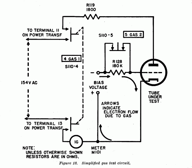
The most important omission is about the specific test for voltage regulators / gas-controlled tubes. A TV-7 tests these tubes using the GAS1 test circuit always at same voltage (150 VAC), this means 0B2 (105 V) will be tested at same voltage as 0A2 (150 V)... perhaps this is not a good idea. Also I have serious doubts about the use of AC voltage to test these tube-types. A VR tube is not a rectifier tube, rectifiers and diodes are specifically designed to support AC voltages, but this is not true for VR tubes! Also, the shorts test can give false positives, and the gas test false evaluations; these circuits must wait 20 minutes for the tester to warm up and remove some of the residual moisture that make these tests overly sensitive. Mouseover underlined text above and the schematics below for additional info.
Core circuits in a TV-7.
Test circuits in a TV-7.
The missing circuit: TV-7 doesn't have a professional test circuit for VR and thyratrons; nor safe for those tubes when they're tested.
|
|
Power Supply circuit, the core of a tube tester.
(Mouse over schematic below to see explanations)
 |
|
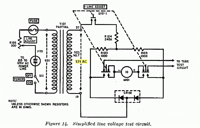
Line
Voltage circuit, the fine tuning of a tube tester.
(Mouse over schematic below to see explanations)
 |
|
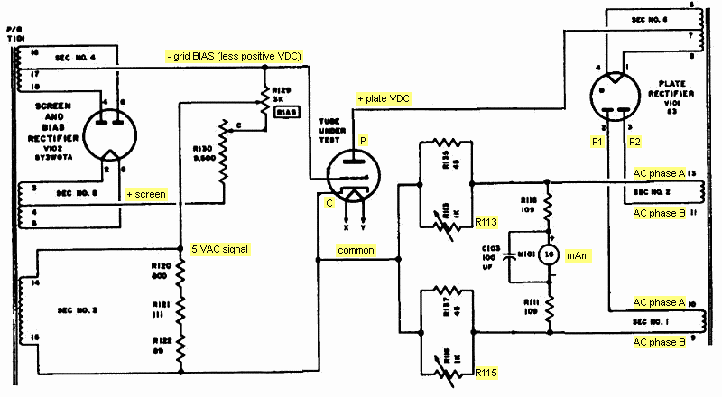
Gm
test circuit connected to a tetrode.
(Mouse over schematic below to see explanations)
 |
|
Gm test applied to a triode. TM 11-6625-274-35 page 16, redesigned simplified schematic.
(Mouse over schematic below to find out why the needle stops in a certain position)
 |
|
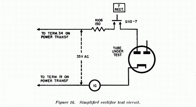
Rectifier
test circuit connected to a diode.
(Mouse over
schematic below to see explanations)
 |
|
Test circuit for gas tube-types; and gas test applied to triodes/pentodes.
(Mouse over schematic below to see explanations)
 |
|
Shorts
& Noise test.
(Mouse over each schematic below to see explanations)
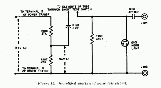 |
 |
|
The TV-7's missing circuit: a correct test circuit for VR tubes & thyratrons.
Hickok solution in the TV-7's "big brother":TV-7 tests the special gas tubes as if they were neon lamps, using the general gas test circuit for triodes and pentodes, thus performing a botched test of those tubes. The circuit below can be considered as the missing circuit, the one that should have been applied. It uses adjustable DC, that's mandatory to test VR tubes. TV-2 is not so "cute", and easy to use like a TV-7; but TV-2 is on a higher level, close to tube analyzers.
|
Heathkit solution; as usual, specific and straightforward:These circuits emulate the real working circuits of the tubes, adding adjustments and the meter in the correct place. Why make it complicated when simple is better? Excellent Heathkit solution.
|
|
|


