BIAS
control settings and voltage applied to the tube under test
| BIAS |
Volts |
| 1 |
-0.0 |
| 2 |
-0.1 |
| 3 |
-0.1 |
| 4 |
-0.2 |
| 5 |
-0.3 |
| 6 |
-0.4 |
| 7 |
-0.5 |
| 8 |
-0.6 |
| 9 |
-0.7 |
| 10 |
-0.8 |
|
| BIAS |
Volts |
| 11 |
-0.9 |
| 12 |
-1.1 |
| 13 |
-1.3 |
| 14 |
-1.4 |
| 15 |
-1.6 |
| 16 |
-1.8 |
| 17 |
-2.0 |
| 18 |
-2.2 |
| 19 |
-2.4 |
| 20 |
-2.7 |
|
| BIAS |
Volts |
| 21 |
-2.9 |
| 22 |
-3.1 |
| 23 |
-3.4 |
| 24 |
-3.7 |
| 25 |
-3.9 |
| 26 |
-4.2 |
| 27 |
-4.5 |
| 28 |
-4.8 |
| 29 |
-5.1 |
| 30 |
-5.4 |
|
| BIAS |
Volts |
| 31 |
-5.8 |
| 32 |
-6.1 |
| 33 |
-6.4 |
| 34 |
-6.8 |
| 35 |
-7.1 |
| 36 |
-7.5 |
| 37 |
-7.9 |
| 38 |
-8.2 |
| 39 |
-8.6 |
| 40 |
-9.0 |
|
| BIAS |
Volts |
| 41 |
-9,4 |
| 42 |
-9.8 |
| 43 |
-10.2 |
| 44 |
-10.6 |
| 45 |
-11.1 |
| 46 |
-11.5 |
| 47 |
-11.9 |
| 48 |
-12.4 |
| 49 |
-12.8 |
| 50 |
-13.3 |
|
| BIAS |
Volts |
| 51 |
-13.7 |
| 52 |
-14.2 |
| 53 |
-14.6 |
| 54 |
-15.1 |
| 55 |
-15.6 |
| 56 |
-16.1 |
| 57 |
-16.5 |
| 58 |
-17.0 |
| 59 |
-17.5 |
| 60 |
-18.0 |
|
| BIAS |
Volts |
| 61 |
-18.5 |
| 62 |
-19.0 |
| 63 |
-19.5 |
| 64 |
-20.1 |
| 65 |
-20.6 |
| 66 |
-21.6 |
| 67 |
-21.6 |
| 68 |
-22.2 |
| 69 |
-22.7 |
| 70 |
-23.2 |
|
| BIAS |
Volts |
| 71 |
-23.8 |
| 72 |
-24.3 |
| 73 |
-24.8 |
| 74 |
-25.4 |
| 75 |
-25.9 |
| 76 |
-26.5 |
| 77 |
-27.0 |
| 78 |
-27.6 |
| 79 |
-28.1 |
| 80 |
-28.7 |
|
| BIAS |
Volts |
| 81 |
-29.2 |
| 82 |
-29.8 |
| 83 |
-30.4 |
| 84 |
-30.9 |
| 85 |
-31.5 |
| 86 |
-32.1 |
| 87 |
-32.6 |
| 88 |
-33.2 |
| 89 |
-33.7 |
| 90 |
-34.3 |
|
| BIAS |
Volts |
| 91 |
-34.9 |
| 92 |
-35.4 |
| 93 |
-36.0 |
| 94 |
-36.6 |
| 95 |
-37.1 |
| 96 |
-37.7 |
| 97 |
-38.3 |
| 98 |
-38.8 |
| 99 |
-39.4 |
| 100 |
-40.0 |
|
|
| Bias voltages in this table apply for testing tubes on ranges B - C - D - E. Bias voltage selection in range F, instead 0 to -40, is 0 to -4 volts (.1 x). These voltages are ± linearly distributed, due this may differ depending
on unit and its particular potentiometer, don't worry about small differences, but when testing high transconductance tubes, a small difference has noticeable effect on the meter. This partially explains the different readings of one unit to another, and remembering here again that a TV-7 is a very
good tube tester but not lab gear.
Since the voltage range covers the full excursion of the BIAS potentiometer, in range F any selected voltage will be less sensitive to knob positioning or BIAS potentiometer mfg tolerances. Range F (model "D" only) is a LOW-BIAS range E, VERY FEW tubes TEST in range F (I doubt they are more than the fingers of one hand). "Range F tubes" have double test line in the Test Data manual, so in a TV-7D/U there are some tubes that can be tested both on range E and F (equivalent to coarse / fine bias voltage test). I'm guessing that the TV-7D/U's range F was proposed to gradually move high transconductance tubes to this particular range due to the high sensitivity of high Gm tubes to small BIAS voltage variations; but maybe they fell short at just -4, IMO it should have been extended up to -16 volts. Another characteristic of range F is that it has the gas test circuit slightly modified (see the testing methods page).
An example of how much the values of above can differ among units (VTVM + 56 Kohm balancing load resistor):
This shows that for high transconductance tubes is mandatory to use a less prone to errors bias voltage scale, IMO "the range F project".
Do not confuse bias (DC) with signal voltage (AC).
The signal voltages applied to the grid are 5 VAC in ranges B, C; 1 VAC in range D; and 0.5 VAC in ranges E, F. All at mains frequency.
|
Mouse over the italicized underlined text above for additional info. |
Meter
divisions and transconductance in 'S' (mA/V) depending on range
Meter
div. |
Ranges...
* E+, read above |
| B |
C |
D |
E |
F* |
| 2 |
0.05 |
0.10 |
0.25 |
0.50 |
0.50 |
| 4 |
0.10 |
0.20 |
0.50 |
1.00 |
1.00 |
| 6 |
0.15 |
0.30 |
0.75 |
1.50 |
1.50 |
| 8 |
0.20 |
0.40 |
1.00 |
2.00 |
2.00 |
| 10 |
0.25 |
0.50 |
1.25 |
2.50 |
2.50 |
| 12 |
0.30 |
0.60 |
1.50 |
3.00 |
3.00 |
| 14 |
0.35 |
0.70 |
1.75 |
3.50 |
3.50 |
| 16 |
0.40 |
0.80 |
2.00 |
4.00 |
4.00 |
| 18 |
0.45 |
0.90 |
2.25 |
4.50 |
4.50 |
| 20 |
0.50 |
1.00 |
2.50 |
5.00 |
5.00 |
| 22 |
0.55 |
1.10 |
2.75 |
5.50 |
5.50 |
| 24 |
0.60 |
1.20 |
3.00 |
6.00 |
6.00 |
| 26 |
0.65 |
1.30 |
3.25 |
6.50 |
6.50 |
| 28 |
0.70 |
1.40 |
3.50 |
7.00 |
7.00 |
| 30 |
0.75 |
1.50 |
3.75 |
7.50 |
7.50 |
| 32 |
0.80 |
1.60 |
4.00 |
8.00 |
8.00 |
| 34 |
0.85 |
1.70 |
4.25 |
8.50 |
8.50 |
| 36 |
0.90 |
1.80 |
4.50 |
9.00 |
9.00 |
| 38 |
0.95 |
1.90 |
4.75 |
9.50 |
9.50 |
| 40 |
1.00 |
2.00 |
5.00 |
10.00 |
10.00 |
|
Meter
div. |
Ranges...
* E+, read above |
| B |
C |
D |
E |
F* |
| 42 |
1.05 |
2.10 |
5.25 |
10.50 |
10.50 |
| 44 |
1.10 |
2.20 |
5.50 |
11.00 |
11.00 |
| 46 |
1.15 |
2.30 |
5.75 |
11.50 |
11.50 |
| 48 |
1.20 |
2.40 |
6.00 |
12.00 |
12.00 |
| 50 |
1.25 |
2.50 |
6.25 |
12.50 |
12.50 |
| 52 |
1.30 |
2.60 |
6.50 |
13.00 |
13.00 |
| 54 |
1.35 |
2.70 |
6.75 |
13.50 |
13.50 |
| 56 |
1.40 |
2.80 |
7.00 |
14.00 |
14.00 |
| 58 |
1.45 |
2.90 |
7.25 |
14.50 |
14.50 |
| 60 |
1.50 |
3.00 |
7.50 |
15.00 |
15.00 |
| 62 |
1.55 |
3.10 |
7.75 |
15.50 |
15.50 |
| 64 |
1.60 |
3.20 |
8.00 |
16.00 |
16.00 |
| 66 |
1.65 |
3.30 |
8.25 |
16.50 |
16.50 |
| 68 |
1.70 |
3.40 |
8.50 |
17.00 |
17.00 |
| 70 |
1.75 |
3.50 |
8.75 |
17.50 |
17.50 |
| 72 |
1.80 |
3.60 |
9.00 |
18.00 |
18.00 |
| 74 |
1.85 |
3.70 |
9.25 |
18.50 |
18.50 |
| 76 |
1.90 |
3.80 |
9.50 |
19.00 |
19.00 |
| 78 |
1.95 |
3.90 |
9.75 |
19.50 |
19.50 |
| 80 |
2.00 |
4.00 |
10.00 |
20.00 |
20.00 |
|
Meter
div. |
Ranges... * E+, read above |
| B |
C |
D |
E |
F* |
| 82 |
2.05 |
4.10 |
10.25 |
20.50 |
20.50 |
| 84 |
2.10 |
4.20 |
10.50 |
21.00 |
21.00 |
| 86 |
2.15 |
4.30 |
10.75 |
21.50 |
21.50 |
| 88 |
2.20 |
4.40 |
11.00 |
22.00 |
22.00 |
| 90 |
2.25 |
4.50 |
11.25 |
22.50 |
22.50 |
| 92 |
2.30 |
4.60 |
11.50 |
23.00 |
23.00 |
| 94 |
2.35 |
4.70 |
11.75 |
23.50 |
23.50 |
| 96 |
2.40 |
4.80 |
12.00 |
24.00 |
24.00 |
| 98 |
2.45 |
4.90 |
12.25 |
24.50 |
24.50 |
| 100 |
2.50 |
5.00 |
12.50 |
25.00 |
25.00 |
| 102 |
2.55 |
5.10 |
12.75 |
25.50 |
25.50 |
| 104 |
2.60 |
5.20 |
13.00 |
26.00 |
26.00 |
| 106 |
2.65 |
5.30 |
13.25 |
26.50 |
26.50 |
| 108 |
2.70 |
5.40 |
13.50 |
27.00 |
27.00 |
| 110 |
2.75 |
5.50 |
13.75 |
27.50 |
27.50 |
| 112 |
2.80 |
5.60 |
14.00 |
28.00 |
28.00 |
| 114 |
2.85 |
5.70 |
14.25 |
28.50 |
28.50 |
| 116 |
2.90 |
5.80 |
14.50 |
29.00 |
29.00 |
| 118 |
2.95 |
5.90 |
14.75 |
29.50 |
29.50 |
| 120 |
3.00 |
6.00 |
15.00 |
30.00 |
30.00 |
|
|
(*) Range
F is in fact a subrange of range E. As very few tubes test on Range F, and as no tubes will
be developed anymore, this range is in fact useless, so don't get obsessed
with model "D", factually this model only adds ease of adjustment.
The transconductance is a dinamycal parameter, the TV-7
shows a transconductance value under testing conditions and NOT
in relationship with the 'S' or 'Gm' data stated on tube manuals (class
A operation at standard voltages). The transconductance 'Gm', also known
as mutual conductance, it is the opposite of resistance, that's why is
named ohm spelled backwards: mho. Was replaced by the international symbol
'S', the siemens, that means "steepness of valve characteristic" (Slope).
The measure of transconductance is the ratio of the current change at the
output as compared to the voltage change at the input. As an easy example,
considering bias at -5 volts the plate current is 48 mA, on increasing
bias 1 volt (-6 volts total) plate current decreases to 40 mA, then Slope
is 8 mA/V. This is exact when performed in the straight central zone of
the characteristic curve of a tube.
This table represents full distributed equivalence values by marked divisions on the TV-7 meter face (based on the 0-120 reading values simplified table that the manufacturer gives for each range in TM 11-6625-274-12, p.18). In fact these Gm values will only casually coincide with true Gm values. BTW and relative to this, don't obsess either with tube testers that have transconductance values marked on their meters, in practice they are only relative numbers, most with little reference to true Gm values, which are stated on tube manuals pages (that also contain the rest of the standardized specifications for each tube type).
Notes:
- 1 mA/V = 1,000 mhos. Table is in S (mA/V), to transform to micromho simply
multiply by 1,000 or see the full sequence of micromho values in the pdf file at the bottom of this page.
- It appears that the "Minimum value" stated in the Test Data manual is the 60% of the
NOS value. As minimum value for 6L6 is "25", the NOS value would be: (25
x 100) / 60 = 41,66 ... ECC82 is "56" then (56 x 100) / 60 = 93,33 ...
ECC83 is "32" so (32 x 100) / 60 = 53,33 ... EL84 is "50" that would be
"84" rounded ... 6146 is "35" then "59" rounded, etc.
|
FILAMENT switches positions
(L/R) → selected SOCKET pins & color
| A |
B |
C |
D |
E |
F |
G |
H |
J |
K |
| P |
R |
S |
T |
U |
V |
W |
X |
Y |
Z |
| None |
1 |
2 |
3 |
4 |
5 |
6 |
7 |
8 |
9 |
| None |
Brown |
Red |
Orange |
Yellow |
Green |
Blue |
Violet |
Grey |
White |
Notes:
- If the combination of letters is reversed on FILAMENT switches, same socket pins
are selected.
- When a octal tube is tested, voltages applied to the Octal test socket can be
easily monitorized on the Loctal test socket as they have the same numbering
scheme, a socket saver with external pins for monitoring is not needed.
- In the same manner as above, any voltage may be tested on any socket, but looking
at the number on the switch position that indicates the number of pin connected,
and keeping in mind the numbering configuration of the test socket selected
for monitoring. Any tube manual informs about the pin numbering scheme
for any socket.
- Except for filament voltage check, cathode is the common reference basis for all
other voltage tests.
- If LINE ADJUST is adjusted at 50 on the meter indication, filament voltage drops
25%; if adjusted to 40, it drops again another 25%, rest of voltages in
the set drops in the same proportion, of course. This may be useful for
adjusting filament voltages that are not represented in the FILAMENT VOLTAGE
positions.
- The above also may be useful with the intention of obtaining a lower PLATE voltage
combined with an increased FILAMENT VOLTAGE position that matches on this
position the nominal filament voltage of the tube to be tested.
|
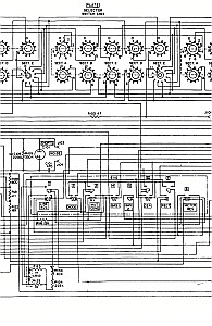
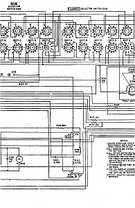
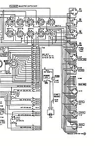
TV-7D/U schematic in 4 sheets to print and join by the edges
 |
 |
 |
 |
Recommended
manuals (at the BAMA site)
and additional docs
- TM 11-6625-274-12 Operator's and Organizational Maintenance Manual for TV-7/U, TV-7A/U, TV-7B/U, TV-7D/U - 11 June 1960 (5.9 MB)
- TM 11-6625-274-35 Field and Depot Maintenance Manual for TV-7/U, TV-7A/U, TV-7B/U, TV-7D/U - 30 June 1960 (1.7 MB)
- TM 11-6625-274-24P Repair Parts and Special Tools List for TV-7A/U, TV-7B/U, TV-7D/U - 28 November 1979 (0.6 MB)
- TB 11-6625-274-12-1 Test Data For Electron Tube Test Set TV-7/U, TV-7A/U, TV-7B/U, TV-7D/U - 17 January 1962 (9.2 MB)
- TO 33AA21-5-31M Supplement Test Data for Electron Tube Test Sets TV-7( )/U - 1 May 1973 (5.8 MB)
|
|
|


